SLS vs SLM: Which Laser Process Fits the Part

SLS sinters. SLM melts. That one word difference decides which materials you can run, whether the part needs support structures, and what the surface looks like when it comes out of the chamber.
Both processes use a laser and a powder bed, which is why they get confused. They are not interchangeable and they do not compete for the same job. This page separates them by what they physically do to the powder, then by surface and tolerance, then by cost, then by the failure modes each one produces.

The one-sentence difference
SLS heats powder until the particles fuse at their contact points, which leaves the part slightly porous and needs no support because the surrounding powder holds it up. SLM melts powder completely into a liquid pool that solidifies into near-full-density metal, which needs support because nothing else holds the overhangs.
Everything downstream follows from that.
What SLS actually does
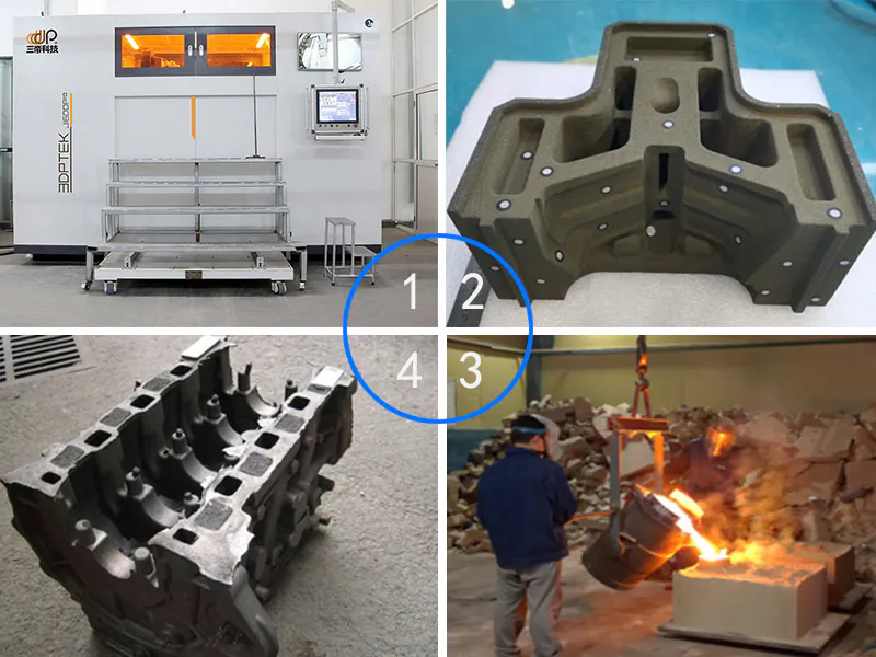
Selective Laser Sintering bonds polymer, wax or coated-sand particles without fully melting them. The laser supplies enough energy to fuse the surface of each grain to its neighbours; the grain core stays solid. The result is a part that is structurally sound at the scale of a casting mould and dimensionally stable enough for pattern work.
Two consequences matter in production. First, no support structures. The powder bed is the support, so a mould or a pattern can be nested anywhere in the build with nothing to cut off afterwards. Second, the surface is granular rather than smooth, because the part is made of partly fused grains rather than a melted pool.
In a foundry, SLS runs coated sand for moulds and cores, and PSB wax for investment casting patterns. The same machine does both — the change is powder, not hardware. That flexibility is the reason the mid-range SLS band is often the first platform a mixed shop buys.

What SLM actually does
Selective Laser Melting takes the metal powder past its melting point entirely. Each layer is a set of overlapping melt tracks that fuse into the layer below, and the finished part is 99 percent dense or better — close enough to wrought for most structural applications after heat treatment.
The support requirement is the operational cost. An overhang needs an anchor, or the melt pool sags. Those anchors are printed in the same metal, cut off by hand or by EDM afterwards, and the cut surfaces usually need finishing. On a part with a lot of overhang, support removal can take longer than the build.
SLM also builds residual stress into the part as a matter of course. The melt pool cools and contracts against the layer below, and the stress accumulates until the part is stress-relieved. Skip that step and the part will move when the supports are cut.
Side by side
| SLS | SLM | |
|---|---|---|
| What the laser does | Fuses particle surfaces | Melts the powder completely |
| Materials | Coated sand, PSB wax, polymers | Stainless steel, tool steel, titanium, aluminium, superalloys |
| Density | Porous at grain scale | 99%+ after processing |
| Support structures | None — the powder bed supports the part | Required on every overhang |
| Post-processing | Depowder, cure, inspect | Stress relief, support removal, machining, HIP where specified |
| Build rate | Higher per layer, no support overhead | Lower — support and stress relief dominate calendar time |
| Best fit | Casting moulds, cores, wax patterns | Finished metal parts, thin walls, lattices |
Where each one fails
Every process has a characteristic failure. Knowing what yours looks like saves a week of arguing with a supplier.
SLS failure modes
Dimensional drift at the build edges. The powder bed near the chamber wall sits at a different temperature from the centre, and parts built at the edge come out slightly larger or slightly warped. Nest the critical dimensions toward the middle of the bed.
Nesting that ignores thermal mass. Packing a bed tightly raises the local temperature and can fuse neighbouring parts together at their closest points. A high-density bed needs a different laser energy profile than a sparse one.
Surface finish taken as a tolerance. The granular surface is not uniform, so a tolerance quoted on a nominal dimension can fail on the surface texture alone. Specify the tolerance and the surface separately.
SLM failure modes
Support removal damage. The most common cause of a scrapped SLM part is not a bad build — it is a chisel in the wrong place. Thin walls and fine lattices are the usual casualties.
Residual stress distortion. A part built without adequate stress relief will bow when the supports are cut. The distortion appears after the build, which is why it gets missed in inspection.
Porosity at the build interface. Where a part sits directly on the build plate, the first few layers see different thermal conditions and are the usual location for lack-of-fusion porosity. Machining allowance on the base solves it.
Surface finish and tolerance in practice
Suppliers quote Ra figures as though they were specifications. They are averages, and the number that matters depends on which face the tolerance sits on.
What “as-built” really means
An SLS mould comes out at roughly Ra 6 to 15 µm. That is consistent across the part because the surface is defined by grain size, not by orientation. A casting mould at that roughness needs no downstream work — the sand surface is reproduced in the casting, which is often an advantage for as-cast texture.
An SLM part comes out rougher on angled faces, because the stair-step of layer thickness shows up wherever the surface is not vertical. Horizontal top faces are the smoothest; a 45-degree face is the worst. The same part can read Ra 8 µm on one face and Ra 20 µm on another, which is why a single Ra number on a metal drawing is not a specification — it is a wish.
Where machining enters
This is where the two processes diverge in cost, not in capability. An SLS mould is used as printed. An SLM part is usually machined on every surface that carries a tolerance or a sealing face, which means fixtures, datums, a machine tool and a second operation.
The practical rule: if the drawing has a tolerance tighter than ±0.2 mm on a metal part, budget for machining before you compare processes. If the drawing is a mould or pattern with a casting tolerance of ±0.5 mm, SLS as-built will hold it.
Cost per part: the comparison that does not get published
Machine price comparisons are easy to find and mostly useless. What decides a project is cost per acceptable part, and that number includes four things the brochure leaves out.
- Machine time per part. SLS wins because there is no support overhead and the powder bed can be fully packed. SLM loses build height to supports and loses calendar time to stress relief.
- Material cost. Metal powder is the expensive consumable, and the unusable fraction depends on the alloy and the reuse policy. Coated sand and PSB wax are cheaper per kilogram by an order of magnitude.
- Post-processing labour. SLS parts go straight to depowdering and inspection. SLM parts need stress relief, support removal, and usually machining.
- Scrap rate. This is the line nobody quotes. An SLS build with a bad nesting parameter wastes powder; an SLM build with a bad support strategy wastes metal and a full machine day.
The pattern is consistent: SLS is cheaper per part at the mould-and-pattern scale, SLM is the only option when the part has to be metal. They are not competing on price. They are competing on whether the part can be a casting or has to be a finished component.
Our SLS cost breakdown works through the consumable arithmetic per build, and the metal system cost guide does the same for SLM including the post-processing line.
The question that actually decides it
Almost every SLS-versus-SLM conversation starts with the process and ends with the material. It should run the other way.
If the part is a mould, a core, or a pattern — something that exists to make a casting — the answer is SLS, because the material is sand or wax by definition. There is no SLM option.
If the part is the casting itself, or a metal component that never sees a mould, the answer is SLM. The exception is a part large enough to exceed the metal chamber but small enough to be cast, in which case printing a sand mould and casting it is both cheaper and faster than printing the metal directly.
That last case is worth stating plainly, because it is where most first projects go wrong. A 400 mm aluminium housing does not need a 400 mm SLM machine. It needs a sand mould in four days and a casting slot.
Which platform does what
Two ranges, ten platforms, no overlap. What follows is what we actually build, not a hypothetical list.
| Range | Model | Build volume (mm) | Process |
|---|---|---|---|
| SLS | AFS-500 | 500 × 500 × 500 | Coated sand and PSB wax |
| LaserCore-5300 | 700 × 700 × 500 | Coated sand and PSB wax | |
| LaserCore-6000 | 1,050 × 1,050 × 650 | Coated sand and PSB wax | |
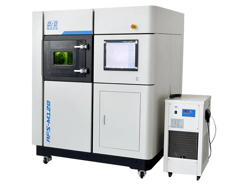
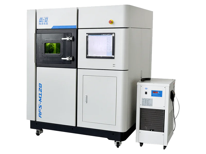
| SLM | AFS-M120 | 120 × 120 × 150 | Metal, single laser |
| AFS-M120X | 120 × 120 × 150 | Metal, two-material gradient | |
| AFS-M120XT | 120 × 150 × 150 | Metal, multi-axis gradient | |
| AFS-M300XAS | 300 × 300 × 250 | Metal, multi-material plus in-process machining |
The ranges share a control system and nothing else. The SLS 3D printer range and the metal 3D printer range carry the full specifications, including the binder-jetting metal platforms that sit alongside the SLM systems.
A selection table you can use in a meeting
Five rows, decided by the part rather than the process. This is the version worth bringing to a specification review.
| The part is… | Process | Because |
|---|---|---|
| A sand mould or core | SLS, coated sand | No support, no tooling, holds casting tolerance as-built |
| An investment casting pattern | SLS, PSB wax | Same platform, powder change, burnout profile already validated |
| Metal, under 300 mm, tolerant of supports | SLM | Near-full density in one operation, machined where it matters |
| Metal, under 120 mm, tight tolerance as-built | SLM single laser | Smallest chamber, best thermal uniformity, least distortion |
| Metal, over 300 mm in two axes | Print the mould, cast the part | SLM cannot clear the chamber; SLS plus a foundry slot can |
Frequently asked questions
Is SLS the same as SLM?
No. SLS fuses powder particles at their surfaces and is used for sand, wax and polymers. SLM melts the powder completely and is used for metal. The difference decides the material, the support requirement and the density of the finished part.
Can SLS print metal?
No. SLS cannot reach the temperature or the melt behaviour needed to consolidate metal powder. For metal, the processes are SLM or binder jetting.
Why does SLM need supports and SLS does not?
Because SLS parts sit in unsintered powder that holds them up. In SLM the powder around the melt pool is not structural, so an overhang needs a printed anchor or it collapses. Support removal is a permanent part of SLM cost.
Which is faster?
SLS, per acceptable part, for anything it can make. There are no supports to remove and the bed can be packed to the edges. SLM loses calendar time to stress relief and build height to supports, so throughput comparisons based on laser speed alone are misleading.
Which surface finish is better?
Neither is good as-built. SLS gives a uniform granular surface around Ra 6 to 15 micrometres. SLM gives a rougher as-built surface with stair-stepping on angled faces, but machines to a far better finish because the material is metal. The question is whether the part needs machining at all.
Related Reading
For the material side of the same decision, 3D printing steel covers the grades that actually run. For the machine side, industrial metal 3D printers lists the seven platforms with build volumes.
The wax side of the SLS range, including what a pattern costs against an injection die, is in wax 3D printer price.Tell us what the part is
Send the geometry, the material and the annual volume. We will tell you which laser process fits — and in the cases where neither does, we will say that instead. A part that should be machined from solid or cast from a printed mould is not improved by printing it in metal.