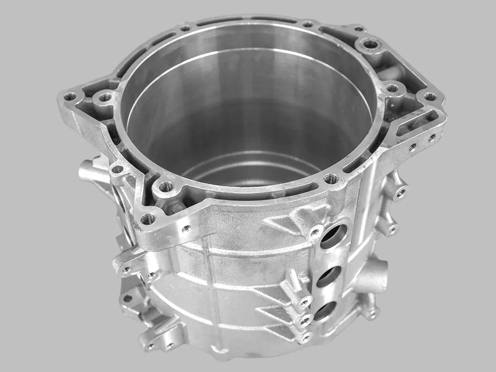
Selective Laser Melting (SLM): Process, Materials and When to Choose It
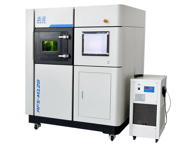
Selective laser melting fuses metal powder layer by layer with a fibre laser, typically 400–1000 W, in an inert atmosphere. Parts come off the plate at 99.5–99.9% relative density with properties close to wrought material after stress relief. It requires support structures, it is slower per part than binder jetting, and it is the only process that can fuse two alloys into one monolithic part.
Key takeaways
- SLM melts; it does not sinter. The distinction matters because it decides whether a furnace is part of the process — in SLM it is not.
- Supports are the hidden cost: they are designed, printed, removed and finished, and they routinely take longer than the build.
- 99.9% relative density is a starting point, not a result — heat treatment is what turns it into usable mechanical properties.
- As-built surface finish is not a mating surface. Every critical face will be machined.
- Gradient and multi-alloy parts are the one capability no conventional process can substitute.
How SLM works, step by step
Five stages, and only the first two are what people picture when they say “3D printing”.
1. Powder layering
A recoater spreads metal powder across the build plate in a layer of 20–60 µm, depending on the alloy and the required surface finish. Layer thickness trades directly against build time: halving it doubles the number of passes for the same height.
2. Laser melting
A fibre laser traces the cross-section, fully melting the powder into the layer beneath. The scan strategy — the order in which areas are filled — is as important as the laser power, because it controls residual stress. Islands, stripes and rotation between layers all exist to stop the part from curling.
3. Support structures
Because the laser melts, the part is anchored to the plate and to anything below it. Overhangs need support, and so does anything that would otherwise sink into the powder. Supports are printed in the same material, welded to the part, and must be cut off afterwards.
This is the stage most purchase decisions underestimate. A part with generous overhangs can carry 20–40% of its mass in supports, all of which is printed, removed, and discarded as scrap.
4. Stress relief and removal
The thermal cycle leaves residual stress in the part. It is stress-relieved in a furnace while still attached to the plate — removing it first would let it distort. Only after that is the part cut from the plate and the supports taken off.
5. Post-processing to tolerance
As-built surfaces carry a roughness of roughly 8–15 µm Ra and a visible layer texture. Interfaces, bores and sealing faces are machined. Heat treatment — annealing, ageing, or hot isostatic pressing where the application calls for it — follows, and it is what establishes the final mechanical properties.
SLM vs SLS vs binder jetting: three names people confuse
The names are similar and the mechanisms are not. One letter separates two processes that differ in material, density and post-processing.
| SLS | SLM | Binder-Jetting | |
|---|---|---|---|
| Energy source | Laser, partially melts | Laser, fully melts | Printhead deposits binder |
| Material | Polymer powder (PA12, TPU) | Metal powder | Metal, sand or ceramic powder |
| Density off the machine | ~100% for polymer | 99.5–99.9% | 55–67% green |
| Furnace required | Nein | No — heat treatment only | Yes — debind and sinter |
| Supports | None — powder bed supports | Erforderlich | Keine |
| Typical surface | 8–12 µm Ra | 8–15 µm Ra as-built | 10–15 µm Ra |
| Best at | Functional polymer parts | Dense metal, fine channels, gradient | Volume metal parts |
DMLS (direct metal laser sintering) is a trade name for the same mechanism as SLM — a laser fully melting metal powder. The name is historical, not metallurgical. If a supplier quotes DMLS and SLM as different processes, ask which one actually melts.
For the comparison that matters commercially — cost, speed and quality against binder jetting — that is covered separately in metal binder jetting versus SLM.
Density and mechanical properties
| Property | Typical as-built range | After heat treatment |
|---|---|---|
| Relative density | 99.5–99.9% | Unchanged, or higher with HIP |
| Tensile strength | Alloy-dependent, typically 90–95% of wrought | Comparable to wrought |
| Yield strength | Often higher than wrought (fine grain) | Adjustable by heat treatment |
| Elongation | Lower than wrought as-built | Recovered by annealing |
| Hardness | Alloy-dependent | Set by the ageing cycle |
Why 99.9% relative density matters
At 99.5% density, 0.5% of the volume is porosity. In a pressure-tight part or a fatigue-limited part, that porosity is where the failure starts. The gap between 99.5% and 99.9% is not cosmetic — it is the difference between a part that passes a leak test and one that does not.
What changes the properties
- Layer thickness. Thinner layers give better surface and finer microstructure, at the cost of build time.
- Scan strategy. Controls residual stress and, through it, distortion and cracking on difficult alloys.
- Powder reuse. Powder degrades with each cycle. Reuse limits are alloy-specific and must be part of the qualified process, not an operational habit.
- Build orientation. Properties are mildly anisotropic. A part built standing up is not identical to the same part built lying down.
Materials available
| Familie | Common grades | Why choose it | Watch out for |
|---|---|---|---|
| Stainless steel | 316L, 17-4PH | Corrosion resistance, good weldability, forgiving process window | 17-4PH needs a defined ageing cycle to reach strength |
| Titan | Ti6Al4V | Strength-to-weight, biocompatibility | Reactive powder, strict atmosphere control, higher cost |
| Aluminium | Al-Si-Mg alloys | Lightweight, good thermal conductivity | Reflective and thermally conductive — harder to melt reliably |
| Tool steel | H13, 4140, 2709 | Moulds and dies, conformal cooling | Cracking risk; preheat and stress relief matter |
| Cobalt-chrome | CoCrMo | Wear resistance, biomedical | Hard to machine after printing |
| Nickel superalloy | Inconel 625, 718 | High-temperature strength | Narrow process window, residual stress |
| Copper and tungsten | Cu alloys, W alloys | Thermal management, radiation shielding | Copper’s reflectivity fights the laser |
More than 30 alloys are qualified across the platform. Open material models matter here: if powder can come from certified third parties and the parameters are published, the cost per part is not tied to a single supplier for the life of the machine.
Supports: the hidden cost
Support design is where SLM projects lose money quietly. The supports are printed in the same alloy, they weld to the part, and removing them is manual work that leaves marks.
| Faktor | Effect | How to reduce it |
|---|---|---|
| Overhang angle | Below 45° from vertical, supports are unavoidable | Reorient the part; add chamfers |
| Support volume | Can reach 20–40% of part mass on a bad orientation | Redesign for self-support where function allows |
| Removal labour | Manual cutting, then grinding or machining | Use block supports where access allows |
| Surface damage | Witness marks where supports met the part | Put supports on non-functional faces |
| Build height | Tall parts need more support and more time | Lay the part down if the geometry permits |
Two practical rules come out of this. First, orientation is a design decision, not a slicing setting — changing it can cut support volume by half. Second, any part with a large unsupported horizontal area should be reviewed before it is quoted, because the supports may cost more than the powder.
When SLM is the wrong choice
It is worth saying plainly where this process loses, because most published material does not.
| Situation | Why SLM loses | Bessere Route |
|---|---|---|
| High annual volume of identical parts | Laser time dominates cost per part | Binder jetting, or conventional tooling |
| Very large single parts | Build envelope and thermal stress both scale badly | Binder jetting, or casting |
| Thin, unsupported walls | Distortion and support damage | Sheet metal, or a different geometry |
| Parts that do not need full density | You pay for a capability you do not use | Binder-Jetting |
| Cosmetic surfaces as-built | Layer texture is always visible | Machining, or a process with a better finish |
Gradient and multi-alloy SLM
Multi-powder feeding allows the composition to change within a single build — in X and Z on a two-powder system, or across all three axes on a four-powder machine. The result is one monolithic part with a hard face and a tough body, or a corrosion-resistant surface over a structural core.
The practical advantage is the joint that no longer exists. A conventional part made from two alloys has a weld, a braze or a mechanical joint between them, and that interface is where failures concentrate. A gradient part has a composition transition instead, with no interface to crack.
Which SLM machine fits which job
| Modell | Bauraum | Laser | Pulver | Built for |
|---|---|---|---|---|
| AFS-M120 | 120 × 120 × 150 mm | 1 × 500 W IPG, 6 m/s | Single alloy | Compact single-alloy production |
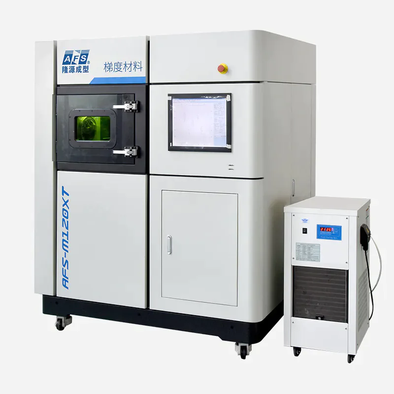
| AFS-M120XT | 120 × 150 × 150 mm | 1 × 500 W IPG | Dual, X + Z gradient | High-temperature and refractory alloys |
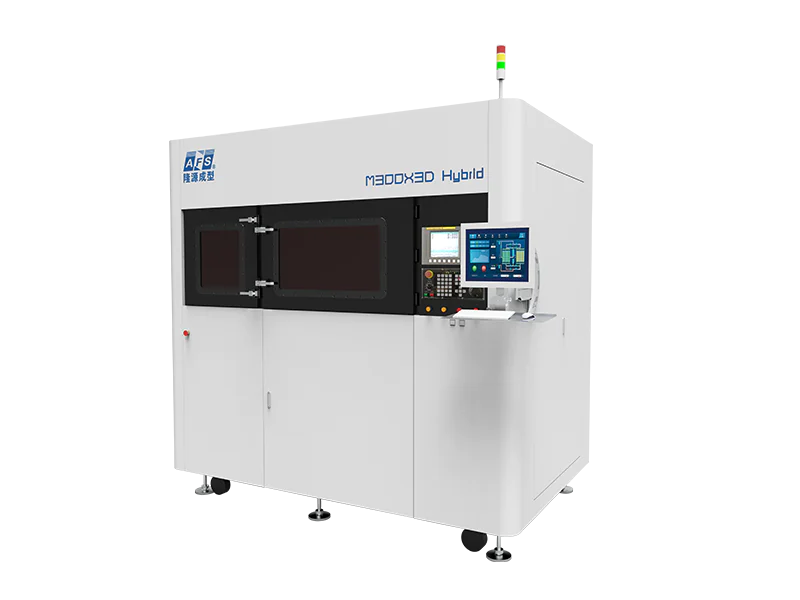
| AFS-M300XAS | 300 × 300 × 250 mm | 2 × 500 W IPG | 4+, X-Y-Z gradient | Hybrid SLM with in-process CNC machining |
The M300XAS machines the part while it is still on the plate, which removes the re-fixturing step for critical bores and faces. The full metal 3D printer range lists every model with its datasheet.
Have a part that needs full density, fine internal channels, or two alloys in one piece? Send the model — we will tell you whether SLM is the right route, what the supports will cost, and where the part should be machined. Metal 3D printing service · Binder jetting metal service
Frequently asked questions
What is the difference between SLM and SLS?
SLS sinters polymer powder and never fully melts it; SLM fully melts metal powder. SLS needs no supports because the powder bed holds the part. SLM needs supports because the melted part must be anchored, and it produces a fully dense metal component rather than a polymer one.
Is SLM the same as DMLS?
Yes in mechanism. DMLS, direct metal laser sintering, is a trade name for a laser that fully melts metal powder — the same process SLM describes. The word “sintering” in the name is historical. If a quote lists both as different processes, ask which one actually melts the powder.
What is the largest part SLM can make?
Build envelopes in this class run from 120 × 120 × 150 mm to 300 × 300 × 250 mm, and larger industrial platforms extend further. The practical limit is often thermal stress rather than envelope: large single sections distort and may need more support than the geometry can tolerate.
How strong is an SLM part compared to wrought metal?
After heat treatment, tensile strength is typically comparable to wrought and yield strength is often higher because of the fine grain structure. Elongation as-built is lower and is recovered by annealing. Hot isostatic pressing is used where the application requires the last increment of density.
Why do SLM parts need supports?
Because the process melts, the part is welded to the plate and to the layers below it. Any overhang steeper than about 45° from vertical has nothing beneath it to fuse to, so support is printed to carry it. Supports are removed by hand or machining afterwards.