
Case Study: Single-Piece Consolidation Cuts Defense Assembly Time 60%

Defense hardware is judged by two clocks: the development clock and the field clock. Development programs must deliver qualified parts faster than the threat evolves, and once fielded, every assembled joint is a potential failure point that maintenance crews pay for in downtime. Both clocks point the same direction: fewer parts, fewer joints, fewer hand-assembly steps. The fastest way to get there is to consolidate a multi-part assembly into a single casting — but conventional tooling has historically made that impossible, because the consolidated geometry cannot be withdrawn from a pattern.
3D printed sand molds remove the withdrawal constraint. Because the mold is printed from the CAD file rather than formed around a pattern, a design team can merge brackets, housings, bosses, and internal passages into one casting that would have required several machined or forged parts before. This case study documents how a defense contractor used that capability to cut assembly time by roughly 60% on a structural program — and why the same approach is spreading across defense casting procurement.
Why Defense Programs Need Part Consolidation
Every part in a defense assembly carries a cost beyond its invoice, which is why design for manufacture and assembly has long pushed toward fewer, more integrated parts. A bracket that could be cast into a housing still needs its own drawing, its own supplier, its own inspection, its own fasteners, and its own place in the assembly sequence. Each joint adds tolerance stack-up, each fastener adds a fatigue and corrosion risk, and each hand-assembly step adds labor and the possibility of error. In a platform that must survive shock, vibration, and thermal cycling, the joints are where failures start.
Consolidation attacks all of those costs at once. A single casting replaces several parts and their fasteners, removes the tolerance stack between them, eliminates a whole set of assembly operations, and — because the casting is designed as one piece — lets the engineer optimize the structural load path instead of optimizing the bolted interfaces. The benefit compounds in defense programs where reliability, weight, and maintainability are contractual requirements, not aspirations.
The obstacle has always been manufacturability. A consolidated part is typically more complex than the sum of the parts it replaces: internal passages, undercuts, and boss geometry that a conventional pattern cannot release. Our traditional vs. patternless analysis explains the tooling logic in detail; the short version is that pattern tooling punishes exactly the geometry consolidation requires. Printed molds remove that punishment, which is why consolidation and digital molds arrive together — the same logic driving part consolidation across advanced manufacturing.
The Challenge: One Part Instead of an Assembly
The program in this case study began as a typical defense structural assembly — a load-bearing housing with several separately machined brackets and mounts bolted to it, plus a set of internal passages that were drilled or added as separate fittings. The assembly worked, but it paid the full consolidation tax: long lead times across multiple suppliers, hours of assembly and alignment labor per unit, and a catalog of joints that every inspection and maintenance cycle had to verify.
The customer’s requirement was direct: deliver the same function as a single cast component, with the brackets, mounts, and internal passages integrated into one piece, and validate it to the same structural standard as the original assembly. On the conventional route that requirement is nearly a contradiction — the integrated geometry includes internal cavities and undercuts that no pattern can produce, and a tooling program to attempt it would run for months at high cost.
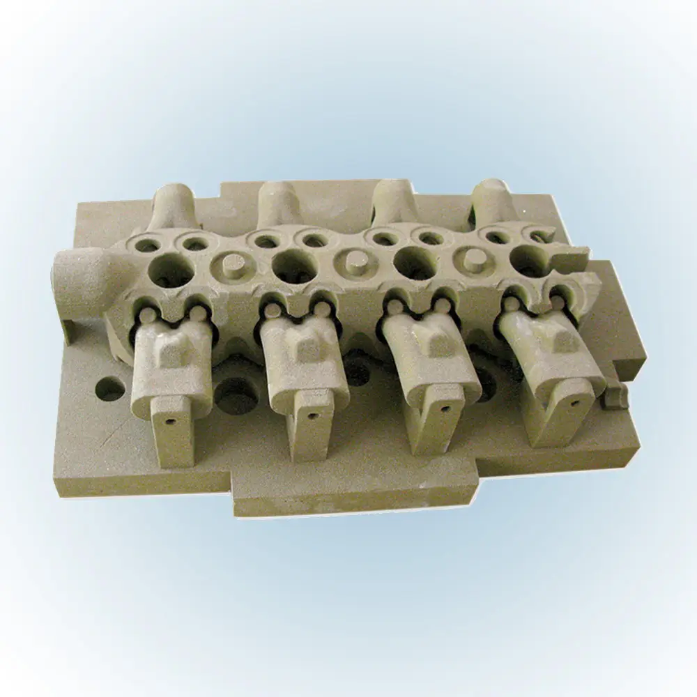
The solution was 3D printed sand molds. The mold and cores were printed directly from the consolidated CAD model, with the complex internal cavity formed by integrated printed cores. That is the same mechanism the knowledge base shows across our industrial programs — for example, a large cylinder block with a complex internal cavity produced with 7 sand cores and 3 sand molds, where optimizing the sand-mold structure simplified assembly, improved positioning accuracy, reduced sand-mold weight, saved labor, and cut cost while achieving integrated molding of the complex core. The consolidated defense housing followed the same playbook.
How Single-Piece Consolidation Works on the Digital Route
Consolidation on printed molds follows a repeatable workflow, documented in our CAD to casting guide:
- Consolidate in CAD. The separate parts are merged into a single model, with bosses, mounts, and passages designed as cast features. This is where the engineer decides what moves from machined to cast — and what the load path should look like without bolted interfaces.
- Design the mold for the consolidated geometry. Because there is no pattern withdrawal, the mold split is chosen for casting soundness and core support rather than for part release. Internal cavities become printed cores.
- Print and assemble the mold. The mold and cores are printed from the file. In the cylinder-block example, the structure was optimized to 7 sand cores and 3 sand molds, which simplified assembly and improved positioning accuracy versus a larger, heavier conventional core package.
- Pour, finish, and verify. The casting runs through conventional gravity or low-pressure casting, machining, and inspection against the CAD model — the same chain any defense casting supplier must run.
That digital nature also changes how revisions are handled after qualification. If a mount point moves or a passage changes during the platform life, the update is a new print and a re-validation — not a tooling modification that stalls the line. For defense programs that run for decades and see periodic upgrades, that means the casting can evolve with the platform instead of being frozen by its tooling. The CAD to casting guide documents how the file-to-part workflow supports this.
The result is a part whose complexity lives in the digital file instead of in the tooling. In practice, the design team merged the bracket and mount geometry into the housing walls rather than bolting on separate parts, and the internal passages were formed by printed cores in a single pour. That inversion is what makes consolidation affordable: in conventional manufacturing, complexity multiplies tooling cost; on the printed route, complexity is nearly free, because the printer produces the mold for the consolidated geometry as easily as for the simple one.
The Results: Assembly Time Down 60%
The consolidated casting replaced the multi-part assembly with a single component, and the measured outcomes covered the whole lifecycle:
| Impact | Original assembly | Single-piece casting |
|---|---|---|
| Parts per unit | Multiple (housing + brackets + mounts + fittings) | 1 |
| Fasteners & joints | Many | None (features cast in) |
| Assembly labor | Hours per unit, alignment required | Cast in place |
| Internal passages | Drilled / separate fittings | Printed cores, as-cast |
| Assembly time | Baseline | ~60% lower |
| Inspection points | Per part + assembly | Single casting, CMM vs CAD |
The 60% reduction came from three sources. First, the assembly operations themselves disappeared — nothing to bolt, align, or torque. Second, the tolerance stack between parts vanished, so no time was spent adjusting joints to fit. Third, the internal passages were formed by printed cores instead of being drilled or assembled, removing a whole machining and fitting sequence.
The structural side held its own. The program validated the same loading cases as the original assembly and passed — with fewer inspection points, because one casting replaces several parts. Casting the brackets and mounts as one piece with the housing means the load path runs through continuous metal instead of through bolted interfaces, and dimensional verification against the CAD model confirmed the consolidated geometry to the drawing. The program validated the same loading cases as the original assembly and passed — with fewer inspection points, because one casting replaces several parts.

Why the Quality Is Certifiable
A consolidated defense casting only earns its place if it can be qualified to the same standard as the parts it replaces. On the digital route, the acceptance evidence is conventional:
- Dimensional verification against the consolidated CAD model with coordinate measuring machines, so the integrated features are proven to the drawing.
- Alloy chemistry verification per the material specification, with spectrometers confirming composition.
- Non-destructive testing — the standard flaw-detection methods applied to a single large casting instead of several smaller parts, which actually simplifies the inspection plan.
- Mechanical testing per the structural standard, on the same alloy and process the original parts used.
Because the casting process itself is conventional sand casting — the mold is just made differently — the material properties and inspection evidence follow the same acceptance rules. That is the complete-chain criterion: a supplier with only a printer can consolidate geometry but cannot qualify it. The producing foundry here runs the full chain, which is the requirement our service provider guide sets out for defense buyers.
Beyond the Housing: The Same Capability Across Defense Hardware
Consolidation is not limited to housings. The same printed-mold capability is already delivering across defense and aerospace hardware:
- Cylinder blocks and structural supports. Large cast-iron blocks with complex internal cavities — the 7-core/3-mold example above — show how integrated cores simplify assembly and improve positioning accuracy on parts with demanding internal geometry.
- Brackets and mounts. Brackets that were previously separate machined parts are cast into housings and frames, removing fasteners and assembly steps. A printed-mold bracket program can go from file to casting in days, which also compresses the development loop for new configurations.
- High-chromium and high-temperature alloys. The process family extends beyond aluminum and cast iron — GLH-5 high-chromium alloy and high-temperature alloys have been produced with 3DP sand casting, and titanium and nickel alloys move through the printed-wax investment route for the hottest sections, covered in the aerospace sand cores article.
For defense programs specifically, the printed route also changes the development economics. A new bracket configuration, a revised mount layout, or a changed passage is a new print — the design can iterate against real castings in days instead of freezing early to protect a tooling investment. The prototyping guide describes this iteration advantage in detail.
There is a supply-chain angle worth noting. Defense procurement increasingly values suppliers who can move from CAD to qualified hardware quickly, because the alternatives — long tooling programs and frozen designs — are precisely what slows modernization. The printed route compresses the critical path from file to first article to weeks, which our digital casting guide frames as the general shift underway in the industry.
What Defense Buyers Should Verify
Before moving a multi-part assembly to a single consolidated casting, defense buyers should check four things:
- Confirm the consolidation target is real. The best candidates are assemblies with many fasteners, alignment-sensitive joints, and internal passages. If the assembly is simple and the joints are not a problem, consolidation may not pay.
- Verify the foundry can run the full inspection chain. Dimensional, chemical, and non-destructive testing must be in-house — see the service provider guide for the questions to ask.
- Design for the printed route. The mold split, core layout, and gating should be designed for the consolidated part by process engineers, not adapted from a machined design. Engaging them early, per the training guide, multiplies the benefit.
- Plan the production handoff. For low volumes, printed molds run the entire program. For higher volumes, the qualified design transfers to conventional tooling without re-optimization — the same two-stage path used across our casting services.
The Economics of Consolidation
The 60% assembly-time figure is the headline, but the full business case is broader, and defense buyers should model all four lines:
Labor. Assembly hours are the most visible saving — the operations that disappeared in this program. For a platform produced in meaningful quantities, labor savings alone can justify the change, and the reduction compounds across every unit built.
Supply chain. A multi-part assembly means multiple suppliers, multiple drawings, and multiple inspection programs. A single consolidated casting means one supplier, one part number, and one qualification package. That simplification shortens the procurement cycle and removes coordination risk — significant in defense, where program timing is contractual.
Reliability. Fewer joints means fewer failure points, fewer inspection points, and fewer maintenance actions. Defense platforms are scored on availability, and availability is directly related to the number of joints in the hardware. The maintenance savings accrue for the life of the platform.
Weight. Consolidation removes fasteners and the material added to support them. In weight-critical defense hardware — where every kilogram affects payload, range, or transport — the saving is often worth more than the assembly time it replaced. Our 3D sand printing cost guide provides the per-part math for modeling these tradeoffs.
There is also a development-side economy that defense buyers undervalue: the iteration loop. On the printed route, a revised mount location or a changed passage is a new print, so the design can be validated against real castings multiple times within a program. That bandwidth is what lets the consolidated design actually reach its potential — the first attempt at a consolidated part is rarely the best one, and the printed route makes the second and third attempts affordable.
When the volume eventually justifies conventional tooling, the qualified design transfers without re-optimization, so the consolidation investment is not stranded — it becomes the production design. The foundry integration blueprint covers how that handoff works on the equipment side.
Frequently Asked Questions
How does part consolidation reduce assembly time? By eliminating the operations themselves. Fasteners are replaced by cast-in features, joints by continuous metal, and internal passages by printed cores — so nothing is bolted, aligned, drilled, or fitted during assembly. In the program documented here, that removed roughly 60% of assembly time.
Why can’t conventional casting produce consolidated parts? Pattern tooling requires the pattern to withdraw from the mold, which limits the geometry to draftable shapes. Consolidated parts with internal cavities and undercuts violate that limit. Printed molds have no withdrawal step, so the consolidated geometry becomes manufacturable.
Is a consolidated casting as strong as the original assembly? Structurally, it is typically better. The load path runs through continuous metal instead of bolted interfaces, and there are no fastener holes to act as stress risers. The program validated the same loading cases and passed, with dimensional verification against the CAD model.
Which alloys work for consolidated defense castings? The same range as conventional sand casting: aluminum, cast iron, cast steel, high-chromium alloys, and high-temperature alloys. Titanium and nickel-based alloys for hot sections move through the printed-wax investment route, described in the aerospace sand cores article.
Is this only for low volumes? No. Printed molds are ideal for development and low-volume production, and the qualified design transfers to conventional tooling when volume justifies it. The consolidation benefit — fewer parts, joints, and inspection points — carries through both routes.
How fast is the first consolidated casting? From file to first casting typically runs in days to weeks, depending on size and complexity. The development loop is what changes most: a revised mount or passage is a new print, so multiple physical iterations fit into the time one tooling cycle used to take.
How do I start a consolidation program? Send the assembly files, the alloy, the quantity, and the structural standard. The engineering team will identify which features consolidate cleanly, propose the mold and core strategy, and return a timeline and inspection plan — request a quote and the process design review starts from the files.
Conclusion
Part consolidation is one of the most direct ways defense programs can cut assembly time, reduce failure points, and compress development schedules — and 3D printed sand molds are what make consolidation manufacturable. The program documented here cut assembly time by roughly 60% by merging a multi-part assembly into a single casting, with internal passages formed by printed cores and every fastener removed from the design.
The mechanism is repeatable across brackets, housings, cylinder blocks, and structural supports, and it carries through to production: the qualified design transfers to conventional tooling when volume grows. For a defense industry measured on both development speed and field reliability, that is the combination that matters.
If you have a multi-part assembly you believe should be one casting, send us a quote request with the assembly files. You will get a consolidation analysis, a casting plan for your alloy, and a schedule measured in weeks.


