
Пример из практики: алюминиевые отливки GIS для применения в системах сверхвысокого напряжения

Gas-insulated switchgear (GIS) is the backbone of high-voltage transmission, and its cast aluminum housings are among the most demanding parts a foundry can be asked to make. Every enclosure seals pressurized SF6 gas around live conductors — a leak is not a cosmetic defect but a safety and reliability failure — so the castings must combine complex geometry, uniform surface quality, and sealing surfaces that pass air-tightness testing. When a manufacturer needs a new GIS component developed for 126 kV to 1,100 kV service, the conventional route means expensive pattern tooling, long lead times, and design changes that cost months.
This case study documents how 3D printed sand molds and low-pressure casting delivered GIS aluminum components for ultra-high-voltage (UHV) applications — from development housings to qualified production parts. It covers the sealing and conductivity requirements that drive the process choices, the measured delivery cycles, and why the printed route converts smoothly into volume production.
Why GIS Castings Are So Demanding
A GIS enclosure does more than protect the switchgear — it contains the insulating gas, positions the live conductor, and provides the sealing interfaces where bays join. Three requirements dominate the casting specification:
- Pressure integrity. The enclosure seals SF6 at operating pressure. The casting must be free of porosity on sealing faces and pass air-tightness testing before assembly — which is why the foundry standard demands zero surface defects and controlled pinhole level on the sealing surface.
- Electrical performance. The internal functional parts are conductive, so the castings must meet conductivity requirements and dimensional accuracy that keeps clearances and tolerances under control at 126–1,100 kV.
- Surface and geometry quality. Uniform surface texture, Class I casting quality, and fully machined interfaces are the baseline — and the internal geometry often includes complex, thin-walled sections that conventional pattern tooling struggles to produce.
The combination pushes traditional foundries to their limit. A housing 1,000 × 1,500 mm weighing 200 kg, or an arm box with cast-in flanges at 34 kg, needs tooling that is expensive to build and slow to change. When the product itself is still being iterated — a new gas bay design, a revised conductor layout, a changed sealing interface — the conventional route locks the design before the castings can be validated, and every revision means re-machining or rebuilding the tooling. Our руководство по цифровому кастингу explains why that tradeoff exists and how printed molds remove it.
The Challenge: Fast, Sealed, and Correct on the First Try
The manufacturer in this program develops GIS components from 126 kV to 1,100 kV — shells, conductors, tanks, cylinders, shielding covers, contact blocks, and arm boxes. For each new product, the requirement was the same: quickly verify structure and performance for iteration and upgrading, while meeting the sealing, conductivity, and Class I casting standards that the final product must hold.
On the conventional route, that demand is almost self-contradictory. High mold-opening cost and long cycles cannot support short-term validation, and the data model is still changing while the tooling is being built. The traditional process simply cannot meet the delivery timelines or the instant data-model modifications that GIS development requires.
The technical bar was set by the product itself. GIS shells encapsulate SF6, so the castings had to pass air-tightness testing and overall flaw detection; the sealing surface had to hold the pinhole standard; the surface texture had to be uniform with zero defects. That is not a prototype tolerance — it is the production acceptance standard, applied from the first trial part. The традиционный анализ против анализа без шаблонов describes the general cost structure these programs avoided.
The 3D Printed Mold Approach
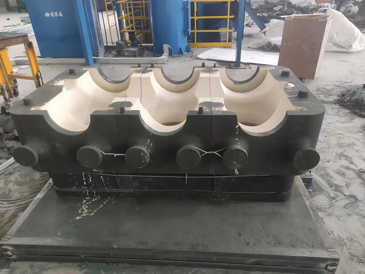
The components were produced with 3D printed sand molds plus low-pressure casting — the process combination used across our high-voltage appliance portfolio. Three properties of the printed route map directly to the GIS requirements:
- Print the mold from the current CAD model. Because the mold is printed directly from the file, every design revision is an edit and a reprint. The development team could change the data model and get a new trial part in days instead of waiting on tooling modifications — the exact “instant modification of data model” the program required.
- Low-pressure casting fills thin, complex sections reliably. GIS housings are thin-walled relative to their size, with sealing flanges and internal features that need controlled filling. Low-pressure casting gives the clean, reproducible fill that Class I quality demands.
- Surface quality and porosity control come from the sand specification and process. The same acceptance tests — air tightness, overall flaw detection, sealing-surface pinhole standard, uniform surface texture — are applied to printed-mold castings, and the process is tuned until they pass.
The producing foundry runs the full chain — process design, printing, casting, machining, and inspection — which is the configuration our Руководство по выбору поставщика услуг по литью в песчаные формы tells power-equipment buyers to verify. The Руководство по переводу чертежей в литьевую форму documents the workflow step by step.
Results: From Trial Part to Production in Weeks
The flagship program was the GIS shell, covering the 126 kV–1,100 kV range. Trial parts were delivered in 5–7 days per set, passed the air-tightness and flaw-detection requirements, and the qualified design then converted directly to mass production. That conversion is the part most people miss: the printed route is not a prototyping dead end. Once the trial part is qualified, the same foundry moves to metal-type low-pressure casting for batch delivery — the printed mold validated the design, and the production tooling runs the volume.
The same pattern repeated across the component family, all in ZL101A aluminum:
| Component | Size | Trial delivery | Производство |
|---|---|---|---|
| GIS shell | 126–1,100 kV range | 5–7 days/set | Metal-type low-pressure, batch |
| Tank | 800 × 600 mm | ~20 days finished | 200 sets/month |
| Cylinder | 500 × 800 mm | ~20 days finished | 200 sets/month |
| Shielding cover | 650 × 150 mm | ~20 days finished | 200 sets/month |
| Contact block | 400 × 850 mm | ~20 days finished | 200 sets/month |
| Housing | 1,000 × 1,500 mm, 200 kg | Weeks (printed route) | Batch after qualification |
| Arm box | 400 × 500 mm, 34 kg | Weeks (printed route) | Batch after qualification |
Every component met the same acceptance criteria: conductivity where required, Class I casting standard, and full machining. The trial-to-production path is why the power-equipment buyer gets the best of both routes — development speed from the printed mold, and volume economics from conventional tooling once the design is frozen.
Conductors: Winning the Order with a 20-Day Validation
A separate program shows how the speed translates into commercial outcomes. A new conductor product needed a finished part within 20 days to verify structural performance for an iterative upgrade, with conductivity requirements and Class I quality maintained. The traditional process could not meet the timing or support on-the-fly modification.
Using 3DP sand molds and low-pressure casting, the finished conductor was delivered in the 20-day window, met the conductivity and Class I standards, and was fully processed. The customer used the validated hardware to win the terminal order — the program reports that the rapid delivery helped the customer win 80% of the terminal order. That is the commercial case for digital molds in power equipment: the developer who can show real, tested hardware first gets the contract.
The conductor case also illustrates the two-stage strategy that runs through all of these programs. Development and first-article production run on printed molds; once qualified, the product moves to metal-type low-pressure casting for batch delivery. The foundry therefore holds both capabilities, and the handoff is seamless because the alloy, the process, and the inspection chain are the same on both routes.
Quality, Testing, and Certification for UHV Service
The acceptance bar for UHV GIS castings is set by the application, not by the manufacturing route. Every casting in these programs was verified against the same standards:
- Air-tightness testing on the SF6 sealing interfaces, with the casting required to pass before assembly.
- Overall flaw detection across the casting, confirming internal soundness.
- Sealing-surface quality held to the pinhole standard, with uniform surface texture and zero surface defects.
- Conductivity verification where the part carries current, checked against the specification.
- Class I casting quality and full machining as the baseline acceptance.
For a UHV casting, the evidence package matters as much as the part. Each program produced a complete record — file version, print parameters, sand and binder specification, pour data, and the inspection results for every acceptance test — so the buyer could audit the trail exactly as with any casting supplier. That documentation is what lets a trial part become a production part: when the customer’s own engineers review the air-tightness records and flaw-detection results, they are reviewing the same evidence they would require at volume.
The sealing and conductivity performance also benefit from the consistency of the printed route. Because every trial mold reproduces the same CAD file, the casting-to-casting variation that normally comes from pattern wear and hand assembly is removed from the development equation. When the design is right, it stays right across the trial batch — which is why the first qualified trial set converts so cleanly into the 200 sets/month production numbers.
None of these change because the mold was printed. That is the point of the approach: the printed mold changes how the mold is made, not how the casting is qualified. The producing foundry applies the same inspection chain — dimensional measurement, chemical analysis, flaw detection — that any power-equipment casting supplier must run, which is the complete-chain criterion covered in our руководство для поставщиков услуг и digital casting workflow.

Why the Printed Route Changes the Development Economics
The numbers in the table above deserve a second look, because the pattern they show is the commercial logic behind the whole approach. Every component that moved through the printed route followed the same economics: the first article exists in days, the acceptance tests decide quickly whether the design is right, and the qualified design carries directly into batch production. There is no point in the cycle where the customer owns an expensive pattern that the next design revision will obsolete.
Contrast that with the conventional route on the same components. A 1,000 × 1,500 mm housing or a 126 kV–1,100 kV shell needs pattern tooling that is large, complex, and expensive — and the tooling is built against a frozen design. If the sealing test or the conductivity requirement forces a change, the tooling is re-machined or rebuilt, and the cycle starts over. In an industry where the product family is constantly expanding — new voltage classes, new bay configurations, new sealing interfaces — that means the tooling budget grows with every product variant, and development throughput collapses under the weight of it.
The printed route replaces that model with a different cost structure, which our Руководство по стоимости 3D-печати на песке quantifies in detail: the mold cost is per part instead of per program, and the development budget buys iterations instead of tooling. That is why the same foundry can serve a whole GIS product family — shells, tanks, cylinders, covers, contact blocks, arm boxes — without a tooling program per variant. The руководство по созданию прототипов explains the same logic for low-volume production.
There is a second economic effect that power-equipment buyers should weigh: risk. On the conventional route, the buyer commits to a large tooling investment before a single casting is validated. If the part fails acceptance, the investment is stranded. On the printed route, the commitment is incremental — one trial set at a time — and the acceptance evidence is in hand before any production investment is made. The GIS shell program shows the ideal shape of that risk curve: a 5–7 day trial, a passed air-tightness test, and then the go-ahead for volume.
For procurement teams building a business case, the Руководство по окупаемости инвестиций в 3D-принтер на песке и break-even calculator provide the numbers behind this decision, whether the question is buying a service or buying a machine.
Lessons for Power-Equipment Buyers
Five lessons from the GIS programs transfer directly to anyone buying cast housings, tanks, or conductors for high-voltage equipment:
- Validate on real castings, not drawings. A GIS housing is defined by its sealing behavior and internal geometry, which only exist once the metal is poured. Printed molds deliver genuine Class I castings in days, so the design can be validated on production-representative hardware — not machined surrogates.
- Keep the design moving until the data is right. The entire advantage of the printed route is that iteration costs days. Structure the program to take multiple physical iterations; that is where the sealing-surface and conductivity issues get found and fixed.
- Require the full inspection chain. Air tightness, flaw detection, conductivity, and dimensional verification must be part of the package. A supplier with only a printer cannot certify a UHV casting.
- Спланируйте передачу производства. The printed mold qualifies the design; metal-type low-pressure casting runs the volume. Confirm the supplier can do both, so the qualified design transfers without re-optimization.
- Use speed as a commercial weapon. The conductor program’s 20-day validation directly helped the customer win an 80% share of the terminal order. When the spec is fixed but the deadline is moving, the supplier that delivers tested hardware first wins.
For foundries evaluating the equipment, the Руководство для покупателей 3D-принтеров для печати песком и план интеграции литейного производства cover machine selection and line integration.
Часто задаваемые вопросы
Can 3D printed sand molds meet GIS sealing requirements? Yes, when the process is specified for it. The GIS shell programs passed air-tightness testing and overall flaw detection, with the sealing surface held to the pinhole standard and zero surface defects. The acceptance tests are applied exactly as they would be on any casting supplier’s route.
Why low-pressure casting for GIS components? Low-pressure casting fills thin-walled, complex sections cleanly and reproducibly, which is what the sealing flanges and internal geometry of GIS housings require. It is the standard production route for these components, and the printed mold feeds the same process.
How fast is a trial GIS part? GIS shells were delivered in 5–7 days per set on the printed route. Tanks, cylinders, shielding covers, and contact blocks reached finished parts in about 20 days including machining. Against conventional tooling cycles, that is the difference between weeks and months.
Is the printed route only for prototypes? No. It is standard for development and first articles, and the qualified design converts to metal-type low-pressure casting for batch delivery — the GIS shell program reports 200 sets/month in production. The printed mold validates the design; conventional tooling runs the volume.
Which alloys are used for GIS castings? The high-voltage programs documented here are ZL101A aluminum, with Class I casting quality and full machining. The same printed-mold process family also serves cast iron, steel, copper alloys, and other aluminum grades across our casting services.
How do sealing and conductivity defects get caught? Through the standard inspection chain: air-tightness testing on the sealing interfaces, overall flaw detection, conductivity verification where the part carries current, and dimensional measurement against the CAD model. The foundry runs all of it in-house.
How do I start a GIS casting development program? Send the CAD model, the voltage class, the sealing and conductivity requirements, and the quantity. The engineering team will return a printed-mold program with a trial timeline and an inspection plan — запросить расценки and the process design review starts from the file.
Заключение
GIS aluminum castings for ultra-high-voltage service combine everything a foundry is tested on: pressure integrity, conductivity, complex geometry, and delivery timing. The programs documented here show that 3D printed sand molds plus low-pressure casting meet every one of those requirements — trial GIS shells in 5–7 days per set, Class I quality, air-tightness and flaw-detection passed, and a clean handoff to 200 sets/month production on metal-type tooling.
The conductor program adds the commercial dimension: a 20-day finished part that helped the customer win 80% of the terminal order. In power equipment, where specifications are strict but programs move fast, the supplier that can show real, tested hardware first is the one that gets the contract.
If you are developing a GIS housing, tank, conductor, or arm box and want to see what printed molds do for your part, send us a запрос на расценки with your CAD file. You will get a printed-mold quote, a casting plan for your alloy, and a trial schedule measured in days.


