
3DPTEK-J2500A Sand 3D Printer: the Cylinder Leaves the Machine, Printing Doesn't Stop
A 2,500 × 1,500 × 1,000 mm binder jetting cell with twelve 400 dpi printheads. Two build cylinders alternate, and a rail-guided transfer car moves the loaded cylinder between the print station, the cleaning station and the curing position, so the print station is never sitting idle while somebody digs a mold out of a box.

One cylinder prints. The other one is somewhere else, being finished.
On a single-cylinder machine, the print head waits while the finished mold is dug out, cleaned and left to cure, and that wait is dead production time on the most expensive asset in your building. The J2500A is designed so that the cylinder, not the machine, is what moves.
The build
The cylinder sits under the gantry and the job prints: twelve 400 dpi printheads, 16–20 seconds per layer, layers from 0.2 mm to 0.5 mm, up to 1,000 mm of Z in a single build.
The handover
A rail-guided car runs the loaded cylinder out of the print station and brings the prepared one in. Because the car does the moving, nobody is rigging a multi-tonne box with an overhead crane while the machine stands still.
The breakout
The mold is broken out at working height, with the piston raised from below and the operator standing on a guarded platform rather than reaching into a pit. Spent sand is collected and returned to your sand supply instead of being swept up as waste.
The cure
The cylinder parks while the mold cures, which frees the cleaning station for the next cylinder. Curing occupies floor along the cell, not the print station.
Why this matters more than print speed. A large sand printer is limited less by how fast it deposits a layer than by how much of the day it is actually printing. On a fully manual setup, breaking out and cleaning one 2,500 mm mold takes the machine out of production for hours. Separating those jobs from the print station is the whole point of the cell.
The stage we remove is the pattern. That is where the weeks went.
Sand casting has always started with a pattern: designed, made, tried in the foundry, corrected, then stored and repaired for as long as the part stays in production. Printing the mould and its cores straight from a file takes that stage out of the critical path, and it is the reason a large casting that used to be quoted in months can be quoted in weeks.
What has to happen before the first pour
- Pattern design and drawing
- Pattern making or machining, in wood, resin or metal
- Pattern trial in the foundry, then correction and rework
- A core box for every internal passage
- Hand ramming, core setting and closing, one mould at a time
- Pour, shake out, fettle
Steps one to four are all tooling. That work runs on its own clock, it is paid for by the batch, and it is the reason a two-off job is often declined rather than quoted. It also has to be stored and repaired for as long as the part stays in production, and re-made the moment the drawing changes.
The same job, without the tooling stage
- You send the STL
- The cell prints the mould, its cores and its gating in one build, up to 2,500 × 1,500 × 1,000 mm
- The cylinder transfers to the cleaning station and the mould is broken out at working height
- The cylinder parks at the curing position; the print station starts the next job
- Assemble, pour, shake out, fettle
No pattern, no core box, no pattern store, no pattern repair. A design revision is a new file, not a new tool, so the second version costs you a print and nothing else. The skill that disappears is the one that takes years to replace.
The point is not print speed. It is that the tooling stage is not shortened, it is absent. What used to sit in front of the first casting, and what used to be charged to the batch, is simply no longer in the sequence. Send us a part you currently quote with tooling and we will print it so you can compare the two routes on your own casting.
The jobs you decline usually go for one of six reasons
Think back over the last year of enquiries and how many of them ended with the same sentence: the tooling does not pay on that quantity. Those enquiries are what this cell is built for, and they are the ones that never appear in a production report because they never became an order.
One-off and small-batch work stops being a tooling decision. The mould is printed from the file you already have, so the first casting no longer carries a pattern's worth of cost on its own.
A revision is a new file, not a new pattern. Nothing is re-machined, re-tried or re-stored, and keeping the old version costs you nothing but disk space.
Passages, undercuts and negative draft that a core box cannot open print as one core. With no joints between segments there is nothing to shift, flash or wash out when the metal arrives.
The cylinder travels on its own rail between the print, cleaning and curing stations. Heavy handling stops competing with the rest of the shop for the overhead crane, and breakout does not stop the machine.
Every mould comes off the same file at ±0.3 mm up to 300 mm. The variation that pattern wear and hand ramming put into a run stops turning up in your scrap figures.
Running the cell is a machine task for a trained operator, not a hand skill that takes years to replace when someone retires. Training is delivered on your own parts during commissioning.
None of these are about print speed. They are about the enquiries that stop at the quotation stage, which is where a foundry actually loses the money. If two or three of the six sound like last month, send us one of those parts.
3.75 cubic metres in one build, and a full metre of Z
2,500 × 1,500 × 1,000 mm is roughly four times the build volume of a 1,200 mm class machine. What that changes is not only how big one mold can be. It is how much of a mold package you can nest in a single job, and how many jobs you can stack in the Z direction before the machine has to stop.
A casting whose mold box does not fit a smaller envelope usually gets split, printed in pieces and bonded or bolted back together. Every joint is a place where the mold can shift under pouring pressure. At 2,500 mm most of those splits simply disappear.
The same envelope that holds one large mold package can hold a set of smaller ones. Because the cell keeps printing while the previous cylinder is cleaned, filling the bed is how you turn build volume into throughput rather than into a longer single job.
A full metre of Z means tall vertical cores print as one body instead of two halves stacked and glued. The tall cylindrical core and the A-frame core in the gallery below are the kind of parts that only make sense when the Z axis is this deep.
Quote the largest casting you make today. If it does not fit, we will say so and point you at the model that does. If it does fit, the next question is whether your building can take the cell, which is what the section above is for.
Four questions decide whether this cell is the right answer
Answer these honestly before you look at a quotation. Three yeses and one maybe is a conversation worth having. Two yeses usually means a smaller platform, or the printing service, will serve you better and for a fraction of the installation.
If the largest dimension is beyond roughly 1,800 mm, the smaller platforms cannot take it at all and this is the class of machine you are shopping in. If your work fits a 1,200 mm or 1,800 mm envelope, a smaller cell will always be cheaper to install and to run.
A production cell earns its keep where jobs come back. If you need a single prototype to prove a design, the printing service gets you a casting without a capital project, and you can buy the machine later with real numbers.
If the hard part of the casting is internal, meaning passages, undercuts, thin ribs or cores that today have to be assembled from segments, printing changes the answer. If the geometry is simple and the constraint is only tonnage, you are buying capacity rather than capability.
About 137 m² as one island, floor load of at least 3 t/m², and a controlled 22–28 °C at 30–50% RH. If the answer is no today, that is a project to plan and budget, not a reason to give up on the idea.
These are the fields the 3DPTEK sand platforms are supplied into, and the J2500A is aimed at the large end of each. If you would rather be told which envelope you need than work it out yourself, send the largest dimensions from your part list and we will answer in one reply, including when the answer is a smaller machine. Request a machine recommendation.
What comes off a cell this size
Real molds and cores, photographed in production. Look at the wall thicknesses, the internal passages and the height of the standing cores: those are the features that decide whether a part is printable at all, or has to be redesigned around a core box.
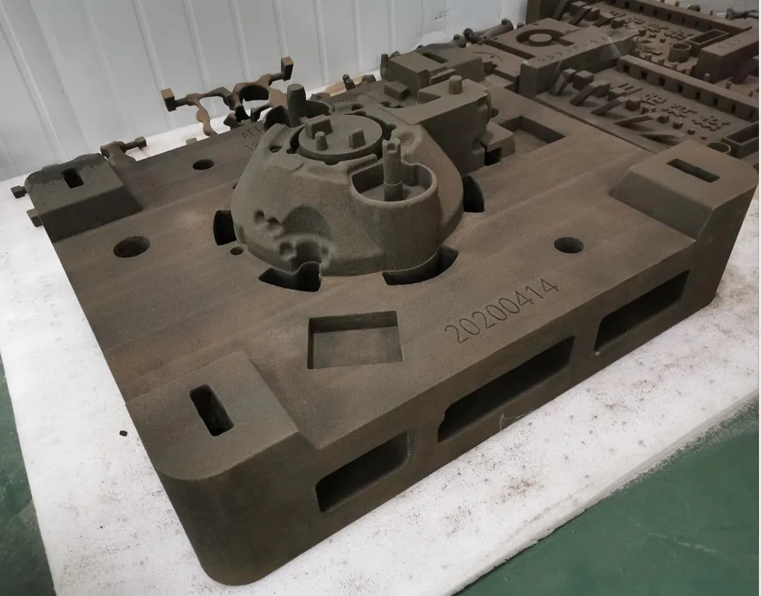
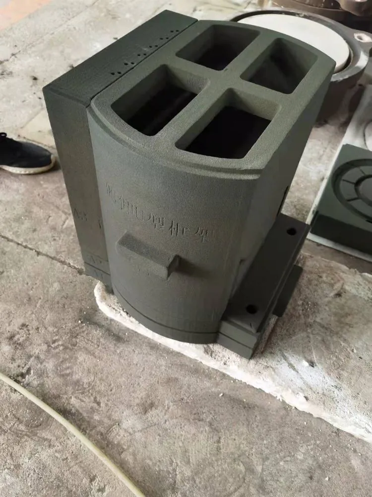
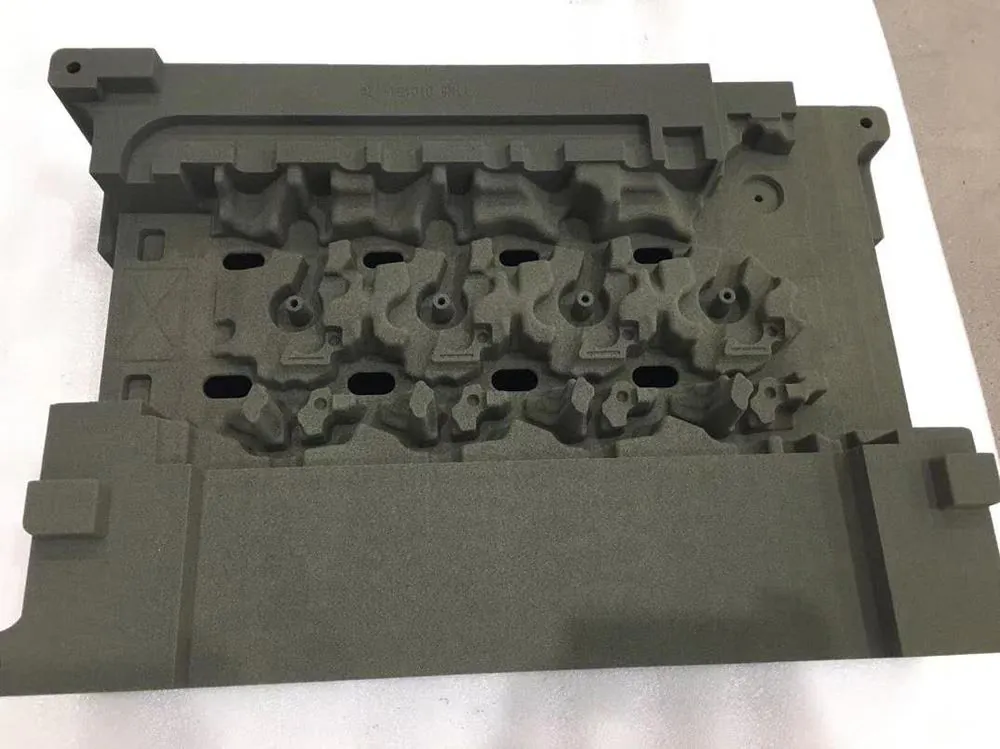
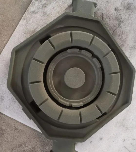
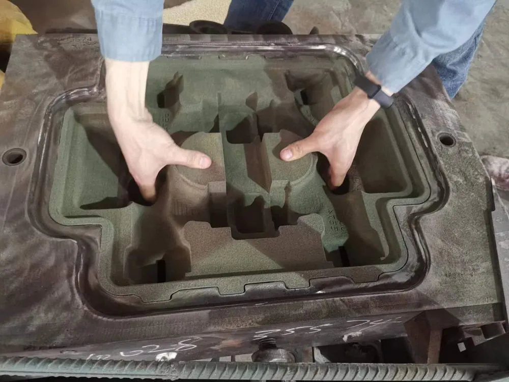
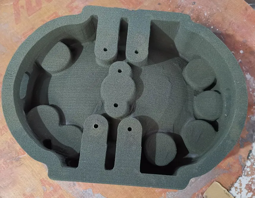
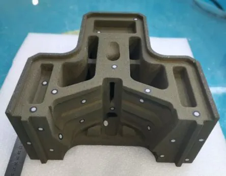
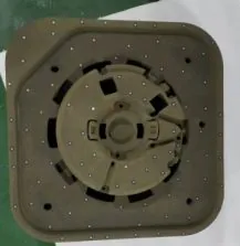
Inspect them yourself. These parts can be examined on a factory visit to a 3DPTEK smart manufacturing centre, where the printers run commercial casting work daily. See the manufacturing centres ou book a visit.
3DPTEK-J2500A technical specifications
Taken from the machine's technical proposal and grouped the way your engineering and facilities teams will actually use it: what it prints, what it prints in, where it goes, and what it needs to run.
Build & printing
| Modelo | 3DPTEK-J2500A |
|---|---|
| Volume de construção | 2 500 × 1 500 × 1 000 mm |
| Cabeças de impressão | 12 |
| Resolução de impressão | 400 dpi |
| Hora das camadas | 16–20 s |
| Espessura da camada | 0,2–0,5 mm |
| Método de impressão | Bidirectional powder spreading, two build cylinders alternating |
Cell & site
| Área de cobertura da célula | 14,800 × 9,280 × 4,250 mm |
|---|---|
| Host unit size | 5,315 × 3,100 × 3,100 mm |
| Peso | ≈40 t total · ≈17 t host |
| Floor load required | ≥3 t/m² |
| Building height | ≥4,5 m |
| Ambient temperature | 22–28 °C |
| Ambient humidity | 30–50% RH |
Accuracy & materials
| Precisão dimensional | ±0.3 mm (≤300 mm) · ±0.5 mm (>300 mm) |
|---|---|
| Areia de moldagem | Areia de quartzo / areia cerâmica |
| Pasta | Resina de furano / resina fenólica |
| Resistência à tração | 1,5–2,5 MPa |
Utilities & control
| Power supply | Three-phase five-wire, AC 380 V ±10% · 50 Hz ±2% |
|---|---|
| Compressed air | 0.6–0.8 MPa · flow ≥1.2 m³/min, clean and dry |
| Control software | AFSWin3DP-L V1.0 |
| Data format | STL |
These are the manufacturer's published figures for the J2500A and are subject to refinement during application engineering for your castings. The connection rating, foundation design and climate load for your site are confirmed in writing with the technical proposal. If a number on this page is critical to your decision, ask us to confirm it.
Furan or phenolic. The machine is not the thing that decides.
The J2500A is specified for both binder chemistries, which matters more than it sounds: it means the decision about which binder suits a given casting stays with your foundry and your sand supplier, rather than being fixed the day you choose a machine.
Quartz sand and ceramic sand
Standard foundry sands, supplied through your existing channels. Surplus sand from the cleaning station is collected and returned to your sand supply, which is where the running cost of a large cell is actually decided.
Furan resin or phenolic resin
Both chemistries are supported on the same platform, so a change in casting mix or in your sand supplier's recommendation does not force a machine change. Printed molds reach 1.5–2.5 MPa tensile strength.
0.2 mm to 0.5 mm layers
Layer thickness is selectable per job, so you can trade build time against surface finish and detail without changing machines. Layer time holds at 16–20 seconds.
±0.3 mm up to 300 mm, ±0.5 mm beyond
Quoted over the feature being measured rather than as a single blanket figure, which is the honest way to state it on a build envelope this large.
Sand selection, layer thickness, orientation and post-processing for your specific castings are set by our application engineers during commissioning, not left to a manual. See the sand mold and core printing service if you would rather have a part printed before committing to a cell.
14.8 by 9.3 metres. Here is what that actually looks like in a bay.
This is not a machine you slide into a corner next to the pattern shop. The print station, cleaning station, curing position and the transfer rail between them occupy 14,800 × 9,280 mm, and the host unit alone is 5,315 × 3,100 × 3,100 mm. Plan the cell as one island with a reserved perimeter, not as a machine with stuff around it.
- The layout is a straight sequence, not a cluster. Cylinders travel between stations on one rail, so the cell needs a clear run rather than a crane path over the top of everything.
- No overhead crane is needed for production. Cylinder movement inside the cell is handled by the transfer car, which is a real difference when your shop already shares one crane between three bays.
- The perimeter is yours to fence. Because the stations sit in a line, the cell can be guarded as a single zone instead of interrupting a walkway every few metres.
- Access for the largest part still has to work. Cured molds up to 2,500 mm leave the cell by forklift or crane from the cleaning station, so keep that edge of the island clear of racking.
The bay outline above is drawn for scale only, to show how much of a typical industrial bay the cell occupies. Your own layout, including aisles and the forklift route, is confirmed in the pre-installation site survey.
Seven numbers to check before you ask anyone for a price
A 2,500 mm sand printer is a building project as much as a machine purchase, and the two items below that catch people out are the climate specification and the floor. Both are engineering problems with known answers, but they belong in the budget from the start, not after the order.
Roughly three times what a compact machine asks for. A standard reinforced industrial slab is not automatically enough, so the foundation is designed against the drawing we supply. Expect either a thickened slab or piling under the cell, depending on what is already there.
This is the requirement that separates the J2500A from a compact printer. It is specified for a controlled 22–28 °C, so the cell area needs real climate control rather than an open bay door. Budget it as part of the installation, not as an optional extra. Ask us what we normally see.
Holding 30–50% relative humidity means drying and dehumidification, not just cooling. It is a tighter window than a compact machine, and it is what protects layer adhesion and dimensional stability on a build that runs long enough to matter.
The cell stands 4,250 mm. The allowance above that covers the sand feed and servicing access.
The host unit is a single lift of about 17 tonnes; the full installation including the platform, stations and cylinders is around 40 tonnes. That drives both the rigging plan and the foundation design.
Three-phase five-wire. The connection rating for your configuration is stated in the technical proposal, because it moves with the options you choose.
Clean and dry, from a normal shop take-off point. Nothing exotic, but it has to be dry, because moisture in the air line ends up in the sand bed.
Issued for your structural engineer, so the slab or piling design is not guesswork.
We come and look at the bay, the access route and the services before the machine is crated.
Power, air and climate loads in one document your facilities team can work from directly.
Installation, commissioning and operator training on your own floor, on your own parts.
This cell is the right answer for some foundries, and an expensive mistake for others
A 2,500 mm cell costs more to install than to buy, in the sense that the building work is the part that surprises people. So be direct with yourself about which of these two columns you are in. If you are in the right-hand column, a smaller machine will do the job for a fraction of the installation.
Choose the J2500A if
- Your castings regularly exceed 1,800 mm in the largest dimension, or you are turning work away because the mold does not fit.
- You have repeat production work, not one-off prototypes. A cell earns its keep on jobs that come back.
- You can give it about 137 m² of floor as one island, with a clear run rather than a shared walkway through the middle.
- Your building can take ≥3 t/m², or you are willing to design a foundation that can.
- You can hold 22–28 °C and 30–50% RH around the cell. If the answer is no, that is a project, not a dealbreaker.
- You want to stop rigging heavy cylinders by hand and stop losing print hours to breakout and cleaning.
- You are replacing large pattern work where the tooling cost and lead time have become the constraint on quoting.
Look at a smaller model instead if
- Your parts fit comfortably in a 1,200 mm or 1,800 mm envelope. You would be paying for floor, foundations and climate control you never use.
- You need an occasional one-off prototype rather than production capacity. Theprinting serviceis usually the better first step.
- Your bay cannot take 3 t/m² and structural work is off the table for the foreseeable future.
- You cannot control the climate in that part of the shop and have no budget to start.
- You need the machine in production next month. This is an installation project with foundation, services and commissioning in the critical path.
Not sure which column you are in? Send us your largest casting dimensions and the bay you have available. We will tell you which envelope you actually need, including when the honest answer is a smaller machine.
Where the J2500A sits in the 3DPTEK range
The J2500A is the large-format platform built around continuous production: a deep envelope, twelve printheads, and the transfer system that keeps the print station fed. If your parts are smaller, or your volume is lower, the models below will do the job for less installation.
| Modelo | Volume de construção | Cabeças de impressão | Posicionamento |
|---|---|---|---|
| 3DPTEK-J2500AThis page | 2 500 × 1 500 × 1 000 mm | 12 | Large-format continuous production, with RGV transfer between the print, cleaning and curing stations. Needs ≥3 t/m², a controlled 22–28 °C and about 137 m² of floor. |
| 3DPTEK-J1800 | 1 800 × 1 000 × 700 mm | 8 | The established mid-volume workhorse for mold and core work, installable in a normal bay with a much lighter foundation. |
| 3DPTEK-J1800S | 1 800 × 1 000 × 700 mm | On request | The latest-generation J1800 with high-speed vibration powder spreading: same envelope at roughly half the weight. |
| 3DPTEK-J1200 | 1 200 × 965 × 800 mm | 3 | Compact production with the deepest Z in its footprint, and the easiest installation in the range: ≥1 t/m² floor load and a 10–30 °C workshop. |
| 3DPTEK-J4000 | 3 800 × 1 850 × 1 000 mm | On request | Oversized molds and cores with sand-box-free flexible forming up to 4 m, at 130–360 L/h. |
| 3DPTEK-J4000Pro | 4 000 × 2 500 × 1 500 mm | 17 | Flagship platform for oversized castings at scale: up to 1,744 L/h and 10+ t of molds per cycle. |
Not sure which one? Send us your part list with the largest casting dimensions, and the bay you have available. We will tell you which envelope you actually need. If the J2500A is the wrong machine for your work, we will say so. Request a machine recommendation.
Questions large-format buyers ask about the J2500A
The questions that come up before an order of this size: whether the building works, how the cell keeps running, what it prints, and what happens after delivery.
Q1What is the build volume and how many printheads does the 3DPTEK-J2500A have?▾
The J2500A prints 2 500 × 1 500 × 1 000 mm in a single build, using 12 printheads at 400 dpi. Layer time is 16–20 seconds, layer thickness is selectable from 0.2 mm to 0.5 mm, and powder is spread in both directions. That is roughly four times the build volume of a 1,200 mm class machine.
Q2How does the two-cylinder transfer system keep the J2500A printing?▾
The build cylinder is a free-standing box rather than a fixture welded into the machine. Two cylinders alternate, and a rail-guided transfer car moves the loaded cylinder out of the print station, through the cleaning station, and on to the curing position, bringing the prepared cylinder back in. The print station therefore does not have to sit idle while a finished mold is dug out, which is what makes continuous production possible rather than theoretical.
Q3What floor and foundation work does the J2500A need?▾
A floor load capacity of at least 3 t/m² and a building height of at least 4.5 m. The installation weighs around 40 tonnes in total, with the host unit at about 17 tonnes. A standard reinforced slab is not automatically sufficient, so we issue foundation drawings for your structural engineer and carry out a pre-installation site survey before the machine ships.
Q4Does the J2500A need a temperature-controlled room?▾
Yes. The J2500A is specified for 22–28 °C and 30–50% relative humidity, which is a tighter window than a compact sand printer and means genuine climate control plus dehumidification around the cell. It is one of the two requirements that most often surprises buyers, along with the floor load, and it belongs in the project budget from the beginning.
Q5How much floor space does the cell take in total?▾
The cell footprint is 14,800 × 9,280 mm, standing 4,250 mm tall. The host unit on its own is 5,315 × 3,100 × 3,100 mm. Because the stations and transfer rail occupy that full footprint, plan the cell as one island with a reserved perimeter rather than as a machine with equipment around it, and keep the cleaning-station edge clear for forklift access to finished molds.
Q6Which sand and binder does the J2500A use?▾
Quartz sand and ceramic sand, bonded with either a furan resin or a phenolic resin system. Printed molds reach 1.5–2.5 MPa tensile strength. Because both binder chemistries are supported on the same platform, the choice of binder stays with your foundry and your sand supplier rather than being fixed by the machine purchase.
Q7How long does a full build take on the J2500A?▾
Build time follows from the part height, the layer thickness and the layer time. At 0.5 mm layers a 1,000 mm tall build is about 2,000 layers; at 0.2 mm layers the same height is about 5,000 layers. At 16–20 seconds per layer you can work out the printing window for your own part from those three published figures. Because the cylinder is swapped rather than emptied in place, a long build does not block the rest of the cell. Send us a part and we will give you a build-time estimate with the quotation.
Q8What dimensional accuracy can I expect on a machine this size?▾
±0.3 mm over features up to 300 mm, e ±0.5 mm beyond 300 mm. Quoting accuracy against the feature size rather than as one blanket number is the honest way to state it across a 2,500 mm envelope, and it is the figure your foundry should be planning machining allowance against.
Q9Can I nest several molds in one build?▾
Yes, and on a cell this size that is usually how the build volume gets used. The envelope holds 3.75 m³, so a large mold package and a set of smaller molds can share one job, and shorter cores can be stacked in the 1,000 mm Z direction. Filling the bed is how you convert build volume into throughput, given that the print station keeps running while the other cylinder is cleaned and cured.
Q10What software does the J2500A use, and what files does it accept?▾
AFSWin3DP-L V1.0, developed in-house and supplied with the machine. It accepts STL model files, handles process and machine parameter setup and motion control, and manages the print, transfer, cleaning and curing sequence across the cell. Operator training is delivered on your own parts during commissioning.
Q11What is included with installation and training?▾
Foundation drawings, a pre-installation site survey and a utility schedule issued ahead of delivery; on-site installation and commissioning; and operator training on your own floor. Application engineering is included as well: sand selection, layer thickness, orientation and post-processing parameters are set for your castings rather than left to a manual. After handover you have warranty coverage, remote diagnostics, preventive maintenance and a sand and binder supply route.
Q12Quanto tempo demora a entrega e a instalação?▾
A test print on your parts typically takes a few working days. The site survey and foundation drawings run in parallel with manufacturing, so the civil and utility work does not have to sit on the critical path, but it does have to start early: on a machine this size the foundation and climate work is the part that sets the date. Ask us for a written schedule against your target production start.
Q13What about spares, consumables and long-term support?▾
The control platform and drives are mainstream industrial components rather than single-source parts, so spares are ordinary catalogue items rather than long-lead imports. Sand and binder are available through normal foundry supply channels, and because the machine supports both furan and phenolic chemistry you are not locked to one consumables route. Support runs through remote diagnostics with escalation to our Beijing engineering team.
Q14How much does the 3DPTEK-J2500A cost, and how do I get a quotation?▾
We quote the J2500A against your requirement rather than publishing a list price, because on a large-format cell the delivered figure depends on the configuration, the foundation and climate work your building needs, and the sand, binder and service scope that go with it. There is no single number that applies to every foundry.
Send us your part list, your largest casting dimensions and the bay you have available and an application engineer will come back with a formal quotation, a machine recommendation and the installation requirements for your site. If it helps, we will print one of your molds first so you can judge the output before any commercial discussion.
Q15How is this different from making a pattern and moulding by hand?▾
The tooling stage is absent rather than shortened. With conventional tooling, a large casting waits on pattern design, pattern making, trial and correction before the first mould is rammed, and that cost is carried by the batch. On the J2500A the mould and its cores are printed from the STL, so a design revision is a new file instead of a new pattern, and small batches do not carry a tooling penalty. What changes on the shop floor is that the job becomes a machine task for a trained operator rather than a hand skill.
More general questions about the technology and the buying process are answered on our FAQ page and in the sand 3D printer buyer's guide.
You do not have to be ready to buy to ask us a question
Most first conversations start with one part, not with a budget. Here is exactly what happens after you send it, and what it costs you.
An STL if you have one, or a drawing if that is what exists. Add the largest casting dimensions and the bay you are working with, and that is enough to start.
On a production machine, not a demonstration one. Free, and under NDA if you want one. Holding the mould answers more questions than any specification sheet we could send you.
A formal quotation, a machine recommendation from an application engineer, and the installation requirements for your site: foundation, utilities, climate load and the rigging plan.
No obligation at any point, and no sales pressure until you have held the part. If the J2500A is wrong for your castings we will say so, including when the right answer is a smaller machine or the printing service. Start with one part.