
Civil works
No piled foundation, no excavation, no grout bed. At ≥1 t/m² the J1200 sits on a standard reinforced workshop slab, levelled on adjustable feet.
A compact binder jetting system with a 1,200 × 965 × 800 mm build envelope and 800 mm of usable Z, deep enough for tall cores printed in one piece. It asks for ≥1 t/m² of floor load and a 10–30 °C workshop, so it goes into the bay you already have instead of one you have to build.

Most sand printing projects are lost at the installation stage, not the printing stage. The J1200 was specified around the constraints that already exist in a working foundry: the floor, the ceiling, the power drop and the air line.
No piled foundation, no excavation, no grouting. The machine is levelled on adjustable feet over a standard reinforced workshop slab, about a third of what a comparable large-format sand printer demands.
No air-conditioned print room and no dehumidifier. The J1200 tolerates the temperature and humidity swing of an ordinary foundry bay, so you are not cooling a room around the machine.
The host lifts with a standard forklift or a light crane. No heavy-rigging contract, no roof opening and no waiting for a crane slot in your district.
A conventional industrial bay clears it. The machine itself stands 2,919 mm; the allowance covers the sand feeding station and servicing access.
One standard three-phase five-wire drop. No substation upgrade and no separate transformer for the machine.
Clean, dry shop air from a normal take-off point, the same supply that feeds your existing foundry equipment.
Host, external platform and two forming cylinders laid out for through-traffic, so a full cylinder can be lifted out without clearing the bay.
Every J1200 order ships with foundation drawings, a full utility schedule and a pre-installation site survey, so your facilities team can sign the bay off before the machine is crated.
The J1200 trades 600 mm of X against the J1800 and gives 100 mm back in Z. If your difficult parts are tall (vertical cores, deep pockets, stacked multi-cavity molds), that is the axis that decides whether a mold is one build or three glued back together.
Three printheads, 5-pass, 400 dpi, bidirectional powder spreading. The 800 mm Z is the deepest axis on any 3DPTEK platform of this footprint, and 100 mm more than the J1800 and J1800S. A vertical core up to 800 mm prints whole, with no split line and no bonded joint to shift during pouring.
The right machine when the part is wide and flat, or when you are feeding high-volume mid-size mold work with eight printheads. Compare the two platforms side by side on the J1800 page.
Cores that stand 700–800 mm print in one piece instead of two halves bonded at a split line, removing a joint that can open, flash or shift under pouring pressure.
Deep cavities and tall bosses no longer force you to lay the mold on its side, which cuts the support structure and the finishing work that comes with it.
Stack two or three cores in the Z direction in a single build. Full-cylinder print time is 10–14 hours, so a stacked job fills close to a full working shift.
The J1200 prints on twin forming cylinders that alternate. While one cylinder is printing, the other is depowdered, cleaned and reloaded, so the machine is not standing idle between jobs. A full cylinder takes 10–14 hours, close to one working shift.
Hand over the mold or core as an STL file. No pattern drawing, no core box, no tooling request.
AFSWin3DP-L V1.0 nests the models, orients them for the 800 mm Z and slices them at 0.2–0.5 mm layers.
Vibration powder spreading lays each layer of quartz or ceramic sand; three 400 dpi printheads deposit furan resin in 5 passes, 18–20 s per layer, spreading in both directions.
The finished cylinder rolls out and the prepared one rolls in. Printing resumes while the first job is depowdered off-machine.
Short cure, then depowder on the cleaning platform. Recovered sand returns to the hopper; molds reach 1.5–2.5 MPa tensile strength ready to assemble and pour.
Automatic sand feeding runs from the hopper through the mixer and screw conveyor, topping up the spreading system on demand, so the operator is not shovelling sand between shifts. Surplus sand is captured by the recovery screw and cleaning platform. See the full sand mold and core printing service workflow.
Eight systems, specified from mainstream industrial suppliers so that spares are ordinary catalogue items rather than long-lead imports. Open a row to read what each one does.
A rigid integrated structure with high assembly accuracy, which is the foundation the rest of the machine is aligned against. The machine is designed to be lifted and moved as one piece.
The spreading carriage lays a uniform layer of foundry sand across the forming plane using a vibration spreading principle. Precision linear guides, a servo motor, reducer and couplings hold the layer flat and repeatable across the full 1,200 × 965 mm plane.
A hopper, mixer, feeding station and screw conveyor deliver prepared sand to the spreading system on demand, so the machine keeps itself supplied through a long build instead of stopping for manual top-ups.
Two forming cylinders alternate: one prints while the other is prepared. Each cylinder is sized to the 1,200 × 965 × 800 mm build volume and runs on precision ball screws with high-accuracy servo motors, guided by linear rails and sealed against sand ingress.
A recovery frame, recovery screw and cleaning platform capture unused sand as the finished cylinder is broken out. Recovered sand goes back into the supply, which is where a sand printer's running cost is actually decided.
The printheads are fed by a closed, negative-pressure binder circuit. Holding the binder at a slight negative pressure keeps the nozzle face clean and the jetting stable across a 10–14 hour build, which is what protects dimensional accuracy over a long job.
A single PLC communicates with the industrial PC, sequences every motion axis and actuator, reads the position and level sensors and applies the interlocks that let the machine run unattended. If a condition goes out of range during a build, the system raises an automatic alarm rather than printing on.
The controller, drives and sensors are mainstream industrial components available through normal distribution channels, so spares do not depend on a single source.
Developed in-house and supplied with the machine. It handles process parameter setup, motion logic control and machine parameter setup.
Taken from the machine's technical proposal. Printing parameters, materials and the full facility schedule: everything your engineering and facilities teams need to plan the installation.
| Model | 3DPTEK-J1200 |
|---|---|
| Volume bangunan | 1.200 × 965 × 800 mm |
| Cylinder configuration | Two forming cylinders, alternating |
| Kepala cetak | 3 |
| Resolusi cetak | 400 dpi |
| Kecepatan cetak | 18–20 detik per lapisan |
| Metode pencetakan | Bidirectional powder spreading, 5-pass |
| Machine footprint | 7,825 × 6,619 × 2,919 mm |
|---|---|
| Machine weight | ≈12 t (host + external platform + 2 forming cylinders) |
| Host weight | ≈3,5 t |
| Floor load required | ≥1 t/m² |
| Building height | ≥4,5 m |
| Ambient conditions | 10–30 °C · 30–85% RH |
| Power supply | 380 VAC / 50 Hz / 10 kW, three-phase five-wire |
| Compressed air | 0.6–0.8 MPa · flow ≥1.2 m³/min, clean and dry |
| Ketebalan lapisan | 0,2–0,5 mm |
|---|---|
| Ketepatan dimensi | ±0.3 mm (≤300 mm) · ±0.5 mm (>300 mm) |
| Waktu pencetakan silinder penuh | 10–14 h |
| Kekuatan tarik | 1,5–2,5 MPa |
| Pasir cetak | Quartz sand / ceramic sand |
|---|---|
| Pengikat | Furan resin |
| Perangkat lunak pengendali | AFSWin3DP-L V1.0 |
| Model input | STL |
Specifications are the manufacturer's published figures for the J1200 and are subject to refinement during application engineering for your specific castings. If a number on this page is critical to your decision, ask us to confirm it in writing against the current datasheet.
Four costs decide whether a sand printer ever gets installed, and none of them appear on the quotation. The J1200 was specified to remove all four.
No piled foundation, no excavation, no grout bed. At ≥1 t/m² the J1200 sits on a standard reinforced workshop slab, levelled on adjustable feet.
No air-conditioned enclosure and no humidity control. 10–30 °C and 30–85% RH is what a normal foundry bay already is.
At ≈3.5 t the host lifts with a forklift or a light crane. No heavy-crane contract, no roof opening, no production shutdown to get it in.
Molds and cores print straight from CAD. No pattern tooling, no core boxes, no pattern storage, no pattern wear to repair. A bespoke pattern set has to be designed, cut, finished, stored and repaired for as long as the part stays in production.
When the mold no longer waits on a pattern, weeks of lead time collapse into hours. Work that was uneconomic at low volume becomes quotable the same day the drawing arrives.
The file does not care about batch size. Print a single replacement core on Tuesday and a production run next week from the same STL, with no tooling decision in between.
Every mold is printed from the same file at ±0.3 mm, so the variation that pattern wear introduces into a run disappears from the foundry's scrap figures.
We quote against your requirement rather than working from a list price, because the delivered configuration depends on your parts, your throughput target and the sand and binder supply you want. Send us your part list or a single STL and an application engineer will come back with a formal quotation and a machine recommendation.
Real production output, not renders: large-format mold packages, cores with internal passages no core box can open, and the impeller and ring cores that have to print as one body.

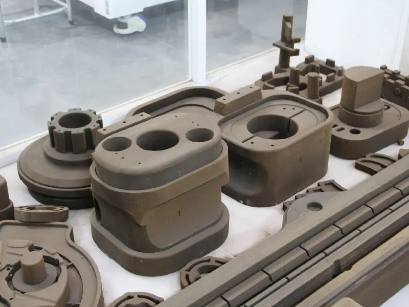
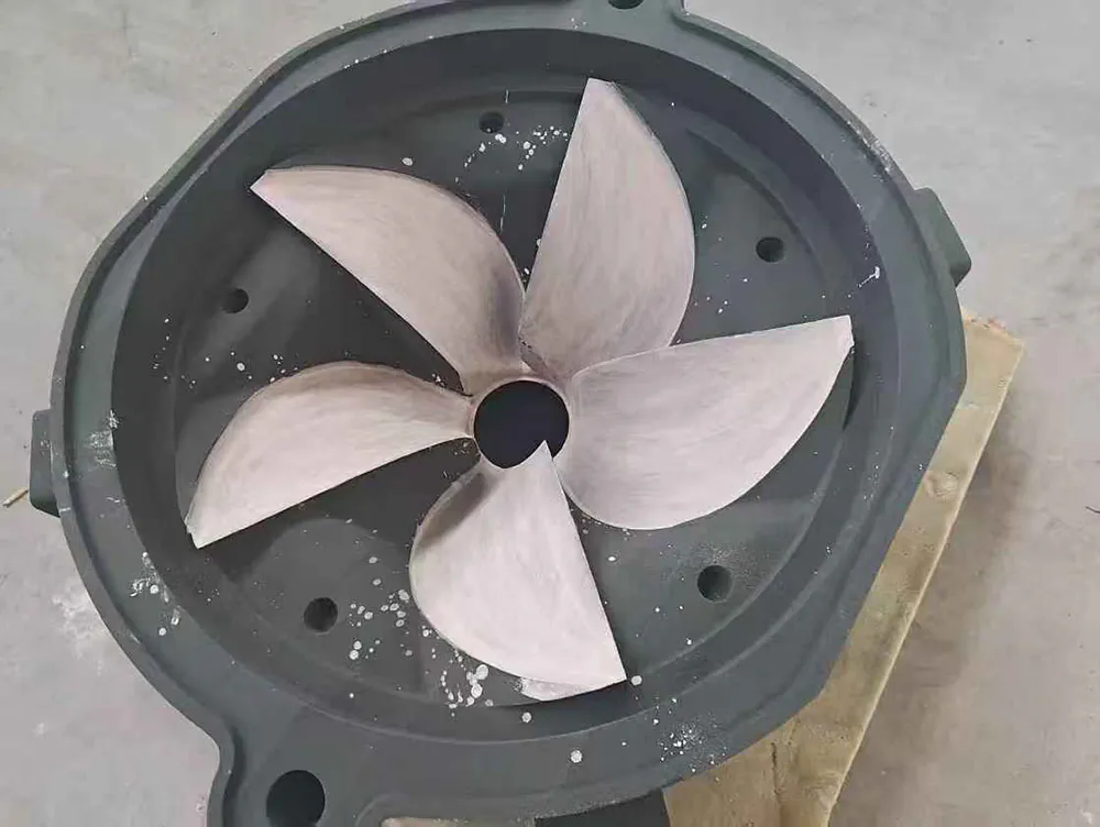

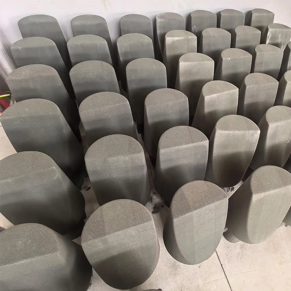

Inspect them yourself. These parts can be examined on a factory visit to a 3DPTEK smart manufacturing centre, where the printers run commercial casting work daily. See the manufacturing centres atau book a visit.
Binder jetting sand printing is used wherever a metal casting has to exist before the tooling does, or where the tooling would never pay for itself.
Structural and engine-adjacent castings where geometry is complex, volumes are low and every iteration costs engineering time.
Aerospace castings →Low-volume, high-mix components produced without a tooling trail, and spare parts printed on demand years after the original pattern was scrapped.
Engine blocks, housings and transmission cases, with mold packages and integrated cores printed as one build for prototype and medium-batch programmes.
Automotive castings →Propellers, pump bodies and valve castings in corrosion-resistant alloys, where internal flow channels drive the mold design.
Marine, pumps & valves →Heavy, chunky castings whose patterns are large, expensive and slow to modify when the design moves.
Construction machinery →Universities and materials laboratories that need a real casting to test, not a simulation, and cannot fund a pattern for a one-off experiment.
Artistic and architectural castings with organic, undercut or freeform geometry that conventional pattern-making cannot reproduce.
Art & architecture →Jobbing foundries using printed molds to take on short-run and urgent work without investing in tooling for every enquiry.
Sand mold & core service →The J1200 is designed and built against the Chinese national standards covering casting sand mold 3D printing equipment, foundry machinery, additive manufacturing terminology and data interfaces, and machine-tool safety. This is the list your engineering team will ask for.
GB/T 42156-2023 Casting sand mold 3D printing equipment: general technical specification GB/T 25711-2023 Foundry machinery: general technical specification GB/T 35351-2025 Additive manufacturing: terminology GB/T 14896.7-2015 Special-purpose machine tools: terminology, part 7: additive manufacturing machine tools GB/T 25632-2024 Additive manufacturing machine tool software data interface format GB/T 41508-2022 Additive manufacturing: general rules, purchase requirements for AM parts GB 26503-2011 Rapid prototyping machine tools: safety protection technical requirements GB/T 5226.1-2019 Electrical safety of machinery: electrical equipment of machines, part 1: general requirements GB 5083-2023 General rules for safety and health design of production equipment GB 50231-2009 Construction and acceptance of mechanical equipment installation engineering: general specification GB/T 17974-2017 Desktop inkjet printers: general specification GB/T 7932-2017 Pneumatic fluid power: general rules and safety requirements for systems and components GB/T 6576-2002 Machine tool lubrication systems GB 2894-2008 · GB 2893-2008 Safety signs · safety colours GB 18209.1/.2-2010 Machinery electrical safety: indication, marking and operation of visual, audible and tactile signals and actuators GB 9448-1999 · GB/T 13306-2011 Welding and cutting safety · nameplates The complete standards schedule, the electrical component list and the machine's acceptance test documentation are issued with the technical proposal. Request the J1200 technical proposal.
3DPTEK has been building industrial 3D printing systems since 1994. The sand printers in our own manufacturing centres are the same platform we ship, running commercial casting work every day.
Three decades of industrial additive manufacturing, most of it spent on binder jetting for the foundry industry. The J1200 is a further refinement of a platform family, not a first-generation machine.
Our smart manufacturing centres print commercial molds and cores on 3DPTEK sand printers. Your application parameters are proven on our own floor before they are written into your process sheet.
Sand selection, layer thickness, orientation, gating and post-processing are tuned for your castings by our application engineers, not left to you and a manual.
Motion control, drives and sensors are mainstream industrial components, the printheads are global-brand industrial units, and the pneumatics and electrics are standard parts. Consumables are available from multiple suppliers.
On-site installation and commissioning with operator training, plus foundation drawings and a pre-installation site survey so the bay is ready before the machine lands.
Warranty coverage, remote diagnostics, preventive maintenance and a guaranteed sand and binder supply chain, with a documented escalation path to Beijing.
The J1200 is the compact, installation-light platform with the deepest Z in its footprint. If your parts are wider than 1,200 mm, or your volume needs eight or more printheads, another platform in the range will fit better.
| Model | Volume bangunan | Kepala cetak | Penentuan Posisi |
|---|---|---|---|
| 3DPTEK-J1200This page | 1.200 × 965 × 800 mm | 3 | Compact production with a deep Z. Installs into an existing bay: ≥1 t/m² floor, 10–30 °C ambient, ≈3.5 t host. |
| 3DPTEK-J1800 | 1.800 × 1.000 × 700 mm | 8 | The established entry-production workhorse for mid-volume mold and core work, with 600 mm more X than the J1200. |
| 3DPTEK-J1800S | 1.800 × 1.000 × 700 mm | Atas permintaan | The latest-generation J1800 with high-speed vibration powder spreading: same envelope at roughly half the weight. |
| 3DPTEK-J2500 | 2.500 × 1.500 × 1.000 mm | 12 | High-volume mold and core production where throughput per shift is the deciding number. |
| 3DPTEK-J4000 | 3.800 × 1.850 × 1.000 mm | Atas permintaan | Oversized molds and cores with sand-box-free flexible forming up to 4 m, at 130–360 L/h. |
| 3DPTEK-J4000Pro | 4.000 × 2.500 × 1.500 mm | 17 | Flagship platform for oversized castings at scale: up to 1,744 L/h and 10+ t of molds per cycle. |
Not sure which one? Send us your part list with the largest casting dimensions. We will tell you which envelope you actually need. If the J1200 is the wrong machine for your work, we will say so. Request a machine recommendation.
The questions that come up before an order: sizing, installation, materials, throughput and what happens after delivery.
The J1200 prints 1.200 × 965 × 800 mm per build, using three printheads at 400 dpi. Layer time is 18–20 seconds with 5-pass bidirectional powder spreading, and layer thickness is selectable from 0.2 mm to 0.5 mm. A full cylinder takes 10–14 hours.
They are sized for different parts. The J1200 gives you 1.200 × 965 × 800 mm with three printheads; the J1800 dan J1800S give you 1,800 × 1,000 × 700 mm with eight. So the J1800 family is 600 mm wider for big flat molds, while the J1200 is 100 mm deeper in Z for tall cores, and it is the lighter, easier installation: ≥1 t/m² floor load against 3 t/m², a 10–30 °C workshop against a controlled 22–28 °C, and a ≈3.5 t host against ≈6 t.
Choose the J1200 when your difficult parts are tall or your building is the constraint. Choose the J1800 or J1800S when your parts are wide and your volume is higher.
A floor load capacity of at least 1 t/m² and a building height of at least 4.5 m. There is no piled foundation, no excavation and no grout bed. The machine is levelled on adjustable feet over a standard reinforced workshop slab. We supply foundation drawings and carry out a pre-installation site survey so your facilities team can confirm the bay in advance.
No. The J1200 is specified for 10–30 °C and 30–85% relative humidity, which is what an ordinary industrial bay already provides. You do not need to build or run a dedicated air-conditioned print room, which is one of the larger hidden costs in a sand printing installation.
It removes the split line from tall parts. A vertical core or deep-pocket mold between 700 mm and 800 mm prints as one piece on the J1200, where a 700 mm platform forces you to print it in two halves and bond them, introducing a joint that can shift or flash during pouring. It also lets you stack two or three shorter cores in the Z direction within a single 10–14 hour build.
Quartz sand and ceramic sand, bonded with a furan resin binder system. Printed molds reach Kekuatan tarik 1,5–2,5 MPa, which suits aluminium, copper, iron and steel castings. Surplus sand is recovered and returned to the supply.
The J1200 uses two forming cylinders that alternate. While one cylinder is printing, the other is depowdered, cleaned and reloaded off the machine. When the build finishes, the cylinders are exchanged and printing resumes, so the machine is not idle while a job is being broken out. That is what makes a 10–14 hour cylinder time practical to schedule.
AFSWin3DP-L V1.0, developed in-house and supplied with the machine. It accepts STL model files, handles multi-model assembly, and offers whole-model move/rotate/scale/mirror transforms. It runs on Windows 10 64-bit with 8 GB or more of RAM.
On-site installation and commissioning, operator training on your own floor, foundation drawings, the utility schedule and a pre-installation site survey. Application engineering is included as well: our engineers set sand selection, layer thickness, orientation and post-processing parameters for your specific castings. After handover you have warranty coverage, remote diagnostics, preventive maintenance and a sand and binder supply chain.
Yes, both. Send us an STL and we will print your mold or core on a production machine and ship the result back with our quotation, free and under NDA if you prefer. You can also visit a 3DPTEK smart manufacturing centre to watch the printers running, inspect mold quality and talk to the operators. Request a test print or a visit.
A test print on your parts typically takes a few working days. Foundation drawings and the site survey run in parallel with manufacturing, so the civil and utility work does not sit on the critical path. The machine ships crated from Beijing, and installation and operator training are scheduled with you in advance. Ask us for a written schedule against your target production start date.
Motion control, drives and sensors are mainstream industrial components rather than single-source parts, so spares are ordinary catalogue items. Sand and binder are available from multiple suppliers, so you are not locked to one consumables channel either. Support runs through remote diagnostics with escalation to our Beijing engineering team.
We quote the J1200 against your requirement instead of publishing a list price, because the delivered figure depends on how the machine is configured and on the sand, binder, spares and service scope that go with it. There is no useful single number that applies to every foundry.
Send us your part list and your target throughput and an application engineer will return a formal quotation with a machine recommendation and the installation requirements for your site. If it would help, we will print one of your molds first so you can judge the output before any commercial discussion.
More general questions about the technology and the buying process are answered on our FAQ page and in the sand 3D printer buyer's guide.
Sand printers The full 3DPTEK sand 3D printer range, covering binder jetting platforms from 1,200 mm to 4,000 mm. Layanan Sand mold & core 3D printing service: print one part before you buy a machine. Learning How sand 3D printing works: the process, layer by layer, from STL to pour. Perbandingan 3DPTEK vs ExOne vs voxeljet: how the platforms compare on envelope and throughput. Costing What sand 3D printing costs: machine, consumables and per-part economics. Design The patternless sand casting guide: designing molds that need no tooling.