
Sand Casting
Sand Casting, From Pattern to Poured Part
Sand casting is still the most economical way to make a metal part in the hundreds or low thousands. The variable is not the sand — it is how the mould gets made. We run both routes: traditional pattern-based moulding, and moulds printed directly from CAD with no pattern at all. Send one drawing and we will tell you which route fits, what it costs, and what tolerance you will actually hold.
Sand casting in one paragraph
Sand casting pours molten metal into a cavity formed in bonded sand. The sand is cheap, refractory, and can be reclaimed; the cavity is destroyed when the part is knocked out. That is the whole economics of the process: you pay for a mould every time, but you pay very little for the mould itself.
Everything else — how fine the surface is, how tight the tolerance holds, how thin a wall you can pour — follows from how the cavity was made and how the metal was fed into it. Those two decisions are the ones worth getting right, and they are where this page spends its time.
What comes out of a printed mould
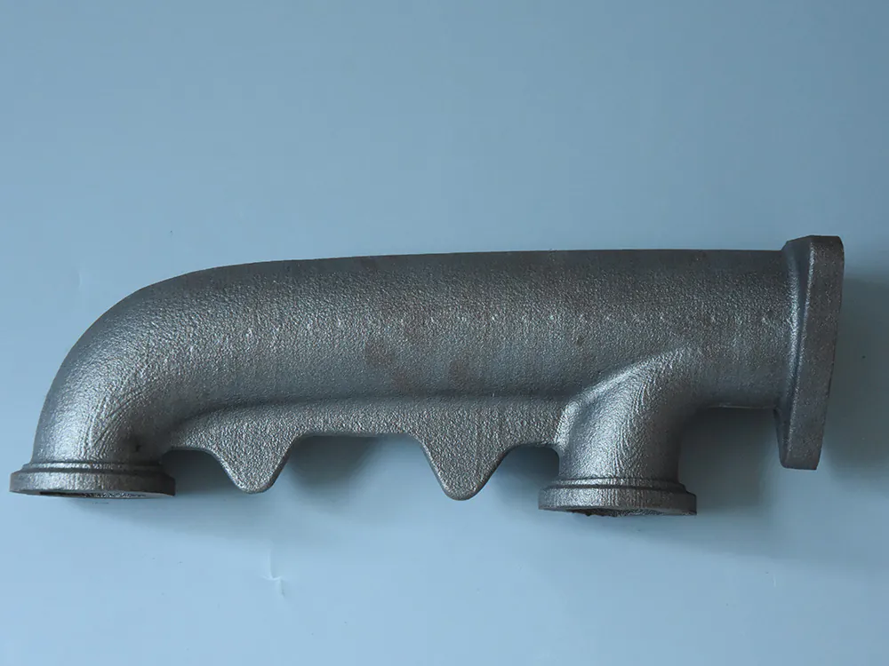
The point of the process is the part, not the mould. These are castings poured from printed sand moulds and cores — engine blocks, pump and valve bodies, impellers, gearbox cases and structural housings, in aluminium, copper alloys, cast iron and cast steel.


From CAD file to a printed mould
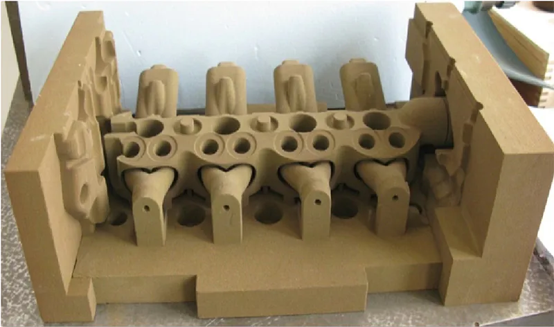
A printed mould is not a pattern. There is nothing to withdraw, so the mould can be built hollow with the cores already in place, and internal passages arrive with no joint line to clean up or flash to remove.
- Mould and cores printed in one piece, directly from the CAD file
- No draft angle, no parting line, no pattern wear
- Geometry that could not be moulded conventionally becomes pour-able
- Design change costs an edit and a re-print, not a new pattern
Moulding, pouring and checking
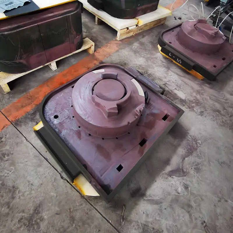
The printed mould is only the start of the casting. It still has to be coated, assembled, poured at the right temperature and rate, cleaned out, heat treated if the alloy calls for it, and checked before it ships.

The four sand casting methods we run
Green sand
Bentonite-bonded sand, rammed in a flask, moulded wet. The cheapest per-mould route and the fastest to repeat, which is why it still carries the bulk of production castings in the 0.5 kg to 200 kg range. We run it on machine moulding lines for volume and by hand for one-offs.
No-bake (furan resin) sand
Sand mixed with a liquid resin and an acid catalyst, cured in the flask without baking. Stronger and more dimensionally stable than green sand, so it takes larger flasks, deeper pockets and heavier sections. This is our workhorse for medium and large parts.
Shell moulding
A thin resin-coated sand shell is cured against a heated pattern. Sharper detail and a better surface than green sand, at a higher mould cost. It suits parts with fine features that must not be washed out at the pour.
Printed sand moulds and cores
No pattern, no flask, no draft. The mould and any internal cores are printed from the CAD file in one piece. The economics only work for small and medium batches — but for those, they work very well, because the pattern cost disappears entirely.
Printed moulds versus traditional pattern work
A pattern is a physical model of your part, plus draft angles and a shrinkage allowance, mounted on a board. It has to be designed, made, tried, and corrected — and its cost is paid again for every new part number, whether you cast one piece or one thousand. Printing removes it: the mould and cores are built by binder jetting directly from the CAD file.
| Comparison | Traditional pattern route | Printed mould route |
|---|---|---|
| Pattern | Required, per part number | Tidak ada |
| Lead time to first part | 10 to 25 days | Hari |
| Design change | Re-make the pattern | Edit the file, re-print |
| Economic batch size | High, pattern amortised | Low to medium |
| Ketepatan dimensi | ±1 mm typical | ±0,3 mm |
| As-cast surface | over Ra50 | under Ra25 |
| Mould construction | Parted, separate cores | One-piece, hollow |
| Sudut draf | Required | Tidak wajib |
| Saluran internal | Cores assembled and located | Printed in place, no joint line |
Where printed moulds stop making sense: when the part number never changes and the volume is high. At that point a permanent pattern pays for itself within a few hundred pieces, and traditional moulding wins on cost per part. We will tell you when that crossover lands for your part rather than sell you the wrong route.
Full service detail, machine specifications and delivery times: Sand mould and core 3D printing.
Pattern design: draft, shrinkage, machining allowance
Three allowances decide whether the casting comes out right, and they are set before anything is poured.
- Draft. Every vertical face of a pattern needs a taper so it can be withdrawn from the sand without tearing the mould wall. Typically 1° to 2° for sand, more on deep pockets. Printed moulds are an exception: they are not withdrawn, so draft is only needed where it helps the metal flow.
- Shrinkage. Metal contracts as it solidifies and cools. The pattern is made oversize by the contraction allowance for that alloy — roughly 1.0% for grey iron, 1.3% to 2.0% for steel, 0.8% to 1.3% for aluminium, 1.5% to 2.1% for copper alloys. Different sections of the same casting cool at different rates, so the allowance is not uniform.
- Machining allowance. Any surface that will be cut afterwards needs extra stock. As-cast accuracy does not support tight tolerances on its own; the allowance is what the machinist removes to reach the drawing. We agree it with you at quotation, because putting too little on is a scrap risk and too much is wasted metal and cycle time.
Gating and feeding
A casting is not filled — it is fed. The difference decides whether the part is sound.
- The gating system carries metal from the ladle into the cavity without turbulence. Entrained air and oxide films from a badly designed sprue become porosity and inclusions that no amount of finishing removes. We size runners and gates to keep the metal velocity in the range where it fills fast without spraying.
- Risers are reservoirs of liquid metal that feed the casting as it shrinks, and they must stay liquid longer than the part does. Correctly placed, shrinkage porosity ends up in the riser instead of in your casting. Chills are used where a heavy section would otherwise cool too slowly.
- Filters sit in the gating to trap slag and loose sand before it reaches the cavity.
Printed moulds change the freedom here: because the mould is built additively, the parting surface and gating layout are not constrained by how a pattern can be withdrawn, so the runner can be routed where the metal wants to go rather than where the pattern allows.
What tolerance will you actually get
Casting drawings are usually specified to a dimensional tolerance grade from GB/T 6414, the Chinese adoption of ISO 8062-3. Lower numbers are tighter.
| Route | Dimensional tolerance grade | Surface roughness, as cast |
|---|---|---|
| Investment casting, silica-sol shell | DCTG 4 to 6 | Ra 3.2 to 6.3 |
| Investment casting, water-glass shell | DCTG 7 to 9 | Ra 6.3 to 12.5 |
| Shell and machine-moulded sand | DCTG 8 to 12 | Ra 6.3 to 12.5 |
| Hand-rammed sand | DCTG 11 to 13 | Ra 12.5 to 25 |
| Our standard working range | CT8 to CT9 | Ra 3.2 to 12.5 |
Across our foundries the standard working figure is CT8 to CT9, with surface roughness of Ra 3.2 to 12.5. Where a part needs better than that, the fix is usually the process route rather than more machining allowance.
As a rule, 4 mm is the floor for a small cross-section, and 10 mm to 15 mm is safer over a large one. Thin walls are where printed cores earn their cost, because the core can be printed without a joint line and without the strength penalty of an assembled one.
Defects and how we prevent them
Casting defects are not random. Almost every one traces back to a decision made before the pour.
| Defect | What causes it | What we do |
|---|---|---|
| Shrinkage porosity | Risers too small or badly placed; heavy sections cooling last | Feed calculation per section, chills on thermal nodes, verified before the pour |
| Gas porosity and blowholes | Moisture and volatiles in the sand; low permeability; poor venting | Sand moisture controlled, vents designed in, binder level kept low |
| Sand inclusion | Mould or core surface breaks down; loose sand in the cavity | Filtered gating, mould wash, cores printed stronger than rammed sand |
| Misrun and cold shut | Metal too cold, wall too thin, filling too slow | Pouring temperature and rate set per alloy; wall thickness agreed at DFM |
| Hot tears | Restraint during contraction; sharp internal corners | Radiused corners, controlled cooling, alloy chemistry verified per heat |
| Dimensional drift | Wrong shrinkage allowance; pattern wear | Allowance set per alloy; printed moulds remove pattern wear entirely |
| Chemical non-conformity | Heat outside spec on Cr, Mo or C | Spectrographic analysis on every heat before pouring, not after |
The plant behind the casting
Process knowledge is not scarce. Capacity is. Here is what actually stands behind a quotation from us.
Melting and pouring
500 kg low-pressure casting machines running a piece every two minutes · 1 t tiltable aluminium melting furnace · 1 t medium-frequency furnace for copper · gravity pouring machines · 30 kg liquid-squeeze casting machine · 958 coated-sand shell core machine at one core per five minutes.
Moulding
10 t resin sand mixer producing no-bake sand to a hardness of 9.5 on the SYS-C scale · machine moulding lines for green sand · hook-type shot blasting · dewaxing and baking furnaces.
Casting capacity by material
| Logam | Processes | Max single piece | Capacity / year | Size range |
|---|---|---|---|---|
| Aluminium | gravity, low pressure, metal-mould low pressure, metal-mould gravity, gypsum-mould precision, liquid squeeze | 1 t | 10,000 t+ | 5 m+ |
| Copper | gravity, low pressure, liquid squeeze, centrifugal, precision | 1 t | 1,000 t+ | 2 m+ |
| Cast steel | shell casting | 1 t | 3,000 t+ | 1.5 m+ |
| Besi cor | shell casting | 1 t | 4,000 t+ | 1.5 m+ |
Machining
Five-axis gantry machining centre at 3 × 4 m · V8 vertical machining centre, 800 × 500 mm, Siemens control with a fourth rotary axis · TH800 horizontal machining centre · slant-bed CNC lathe to Ø450 mm with SINUMERIK 808D · high-precision wire EDM, 630 × 500 × 280 mm · M7140 surface grinder.
Inspection
Coordinate measuring machine, 20 mm to 1,000 mm, maximum length measurement error PEE = 5.18 μm · X-ray flaw detection · 3D laser scanner · optical emission spectrometer · universal testing machine · hardness tester · ultrasonic flaw detector · density tester · vacuum hydrogen meter.
Heat treatment, machining and inspection sit in the same chain as the casting. That matters at the point where something goes wrong: there is one owner for the whole part, not a foundry blaming a machinist and a machinist blaming a foundry. For steel and iron we anneal in a 3.6 × 1.3 × 1.3 m furnace; for aluminium we heat treat in a 2 m diameter furnace, plus a 25 t heat-treatment and ageing furnace.
Our sand 3D printer fleet
We are not only a foundry. We design and build the sand and laser printers that make the moulds, which is why the printed-mould route is a process we control rather than a service we subcontract.
| Mesin | Units | Max build size | Kepala cetak | Efficiency | Mould material |
|---|---|---|---|---|---|
| 3DPTEK-J1200 | in service | 1200 × 965 × 800 mm | 3 | 400 dpi | silica / ceramic sand |
| 3DPTEK-J1800 | in service | 1800 × 1000 × 700 mm | 8 | 400 dpi | silica / ceramic sand |
| 3DPTEK-J1800S | in service | 1800 × 1000 × 700 mm | 4 | 400 dpi | silica / ceramic sand |
| 3DPTEK-J2100 | in service | 2100 × 1290 × 700 mm | 10 | 20 to 25 s per layer | silica / ceramic sand |
| 3DPTEK-J2500 | in service | 2500 × 1500 × 1000 mm | 12 | 16 to 20 s per layer | silica / ceramic sand |
| 3DPTEK-J2500(B) | in service | 2500 × 1500 × 1000 mm | 12 | 16 to 20 s per layer | silica / ceramic sand |
| 3DPTEK-J4000 | in service | 3800 × 1850 × 1000 mm | 16 | 130 to 360 L/h | silica / ceramic sand |
| LaserCore-5300 | in service | 700 × 700 × 500 mm | CO2 laser, 55 or 120 W | 150 to 400 cm³/h | coated sand or PSB powder |
| LaserCore-6000 | in service | 1050 × 1050 × 650 mm | CO2 laser, 120 W | 80 to 300 cm³/h | coated sand or PSB powder |
The fleet covers the size range from a 700 mm SLS platform to a 3,800 mm gantry system, and it runs both routes: binder jetting for sand moulds and cores, dan SLS for coated sand or PSB wax. The LaserCore machines in particular handle both — the same platform prints a sand core or a wax pattern, which is what lets us choose the route on the geometry rather than on which machine happens to be free. Mould sand is qualified in house: silica at 70-140 or 100-200 mesh, or ceramic sand at 100-140 mesh, with furan resin for aluminium, iron and copper and phenolic resin for steel at a 1.8-2.5% addition. Tensile strength 1.5-2.5 MPa, gas evolution 8-15 ml/g at 850 °C.
What we can pour
Metals
Aluminium, copper, cast steel, cast iron, magnesium, high-temperature alloys and titanium.
Aluminium series
1xxx, 2xxx, 4xxx, 5xxx, 6xxx and 7xxx.
Paduan tembaga
10-3 and 9-4 alloys, H62 brass, C90300 tin bronze, and others.
Size and weight
Maximum single casting weight of 1 t in each metal. Envelope to 5 m+ in aluminium, 2 m+ in copper, 1.5 m+ in steel and iron.
Material process know-how is the part of casting that does not scale by buying equipment: we have developed close to 30 material process formulations for casting and five families of binder in house, which is what makes new alloys and new applications a development task rather than a dead end.
Choosing between the methods
Three questions settle it in most cases.
- How many parts, and will the design change? One to a few hundred, or anything still being iterated — printed moulds, because there is no pattern to pay for. Thousands with a frozen design — a permanent pattern and machine moulding, because the pattern amortises and the cost per part drops below anything printing can reach.
- How big and how heavy? Green sand and shell moulding handle small to medium work well. No-bake takes the larger flasks and heavier sections. Beyond roughly 1 t or 5 m, the part has to be split or the process changed — tell us the envelope and we will say which.
- How fine does it have to be? If Ra 25 and CT12 is acceptable, sand casting is the right and cheapest answer. If the part needs Ra 6 or better, or walls below 4 mm, the answer is usually a different process, and we will say so rather than quote you sand casting anyway.
Sand casting or another route?
- Gravity casting
The same printed sand mould, poured without pressure — aluminium and copper to 5 m.
- Low pressure casting
Filled from below for gas-tight housings where a gravity pour can weep.
- Ductile iron casting
Ferrous work in the same moulds: QT400 to QT700, plus ADI.
- Cast steel casting
Carbon, low-alloy and stainless steel, by shell or investment.
- Bronze and brass casting
Copper alloys for bearings, marine hardware and art.
- Precision investment casting
The wax route, when the geometry is thin-walled rather than heavy.
Questions we get before a first sand casting order
What do you need to quote?
A 3D model — STEP, IGES or STL — or a dimensioned drawing, plus the alloy, the quantity and the deadline. An NDA is fine before anything is shared.
How fast is the first part?
Printed-mould work runs from CAD to a poured and heat-treated part in about 20 days on a small batch. Traditional pattern work adds the pattern lead time, which is where the 10 to 25 days usually goes.
What is the smallest batch you will take?
One piece. That is the point of the printed-mould route.
Can you hold tighter than CT8?
Sometimes, and it depends on the feature rather than the part. The honest answer is usually to machine the critical features and cast the rest to CT8–CT9, which is cheaper than chasing a tighter as-cast grade across the whole part.
Do you cast in our sand?
Yes. You can send your own sand and we will run our binder against it, or use our qualified silica or ceramic sand. Ceramic sand reclaims at better than 98%.
What about defects — who pays?
Composition is verified spectrographically before the pour, and dimensional and non-destructive inspection happen before the part ships, with records. If something is out of specification we deal with it rather than shipping it and arguing later.
Can we visit or audit?
Yes. We have ten manufacturing centres, and we will arrange the one that runs the process you are buying.
Do you support first-article trials?
Yes — and for a genuinely new part we will put a foundry process engineer on the trial, for mould coating, assembly, pouring temperature and pour rate. Most first-article failures are process detail, not casting design.
Send the drawing, get a straight answer
Send a model and we will come back within 24 hours with the route we would run, the alloy and tolerance we would hold, the allowance we would leave for machining, and a price. If sand casting is the wrong process for your part, we will say that too.